28. Live Audio Effect Reference
Live comes with a selection of custom-designed, built-in audio effects. These effects range from essential utilities like EQs, compressors, and filters to creative shaping tools such as delays, reverbs, and saturators, among others.
To learn the basics of using effects in Live, check out the Working with Instruments and Effects chapter.
Note that different editions of Live have different feature sets, so some audio effects covered in this reference may not be available in all editions.
28.1 Amp
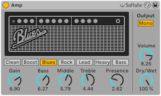
Amp is an effect that emulates the sound and character of seven classic guitar amplifiers. Developed in collaboration with Softube, Amp uses physical modelling technology to provide a range of authentic and usable amplifier tones, with a simple and consistent set of controls.
There are seven amp models to choose from:
- Clean is based on the ”Brilliant” channel of a classic amp from the ’60s. This amp was widely used by guitarists of the British Invasion.
- Boost is based on the ”Tremolo” channel of the same amp, and is great for edgy rock riffs.
- Blues is based on a ’70s-era guitar amp with a bright character. This classic amp is popular with country, rock and blues guitarists.
- Rock is modeled after a classic 45 watt amp from the ’60s. This is perhaps the best known rock amp of all time.
- Lead is based on the ”Modern” channel of a high-gain amp popular with metal guitarists.
- Heavy is based on the ”Vintage” channel of the same amp and is also ideal for metal and grunge sounds.
- Bass is modeled after a rare PA from the ’70s which has become popular with bass players due to its strong low end and ”fuzz” at high volumes.
Although the real-world versions of these amplifiers all have unique parameters, Live’s Amp effect uses the same set of controls for each model. This makes it very easy to quickly change the overall character of your sound without having to make numerous adjustments.
Gain adjusts the level of input to the preamplifier, while Volume adjusts the output stage of the power amplifier. Although Gain and Volume work together to determine Amp’s overall level, Gain is the primary control for the distortion amount. Higher Gain settings result in a more distorted sound. When using the Blues, Heavy and Bass models, high Volume levels can also add considerable distortion.
The Bass, Middle and Treble knobs are EQ controls that adjust the timbre of the sound. As on a real-world amplifier, Amp’s EQ parameters interact with each other — and with the rest of Amp’s parameters — in non-linear and sometimes unpredictable ways. For example, increasing EQ levels can, in some cases, also increase the amount of distortion.
Presence is an additional tone control for mid/high frequencies in the power amp stage. Its influence on the sound varies considerably depending on the amp model used but can add (or subtract) ”edge” or ”crispness.”
The Output switch toggles between mono and stereo (Dual) processing. Note that in Dual mode, Amp uses twice as much CPU.
The Dry/Wet control adjusts the balance between the processed and dry signals.
28.1.1 Amp Tips
Because Amp is modeled on real-world analog devices, its behavior can sometimes be difficult to predict. Here are some tips on getting the most out of Amp:
28.1.1.1 Amps and Cabinets
Guitar amps are designed to be used with accompanying speaker cabinets. For this reason, Amp comes with a companion effect called Cabinet which is designed to be used after Amp in a device chain. If you’re looking for authenticity, we recommend this signal flow. But you can also achieve interesting and exotic sounds by using Amp and Cabinet independently.
28.1.1.2 Electricity
The various circuits in guitar amps work with a continuous and fixed amount of electricity. For this reason, turning up a particular parameter may inadvertently decrease the amount of available energy somewhere else in the amp. This is particularly noticeable in the EQ controls. For example, turning up Treble can reduce the level of bass and midrange frequencies. You may find that you need to carefully adjust a number of seemingly unrelated parameters to get the results you want.
28.1.1.3 More than Guitars
While Amp and Cabinet sound great with guitars, you can get very interesting results by feeding them with drums, synthesizers or other sound sources. For example, try using Amp with Operator or Analog to add analog grit to your digital sounds.
28.2 Auto Filter
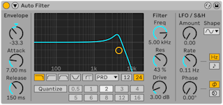
Auto Filter is a filtering effect that modifies the incoming sound by applying frequency-selective filters. It offers various filter types and filter circuit types that emulate classic analog filters. The device’s LFO modulation and envelope follower help create dynamic, tone-sculpting effects. The envelope follower can respond to the filtered signal itself or to an external sidechain input.
28.2.1 Filter Types
You can use the Filter Type chooser to select a filter from ten available types: Low-pass, High-pass, Band-pass, Notch, Morph, DJ, Comb, Resampling, Notch + LP, and Vowel.

The Low-pass filter attenuates frequencies above the cutoff. You can use it to reduce brightness or remove high-frequency content. You can switch the filter between 12 and 24 dB slopes.
High-pass allows frequencies above the cutoff frequency to pass while attenuating lower frequencies. It can be useful for removing low-frequency rumble or thinning out sounds. You can switch the filter between 12 and 24 dB slopes.
The Band-pass filter allows only a specific range of frequencies around the cutoff to pass, attenuating both lower and higher frequencies outside this range. This can be used to isolate a portion of the spectrum or create resonant, focused tones. You can switch the filter between 12 and 24 dB slopes.
Notch attenuates a narrow frequency range while leaving the surrounding frequencies largely unaffected. You can use it to remove specific frequencies or create subtle phasing-like effects. You can switch the filter between 12 and 24 dB slopes.
The Morph filter allows continuous morphing between low-pass and high-pass filtering, with band-pass behavior in between. It has four filter slopes you can choose from: 6, 12, 24, and 48 dB.
The DJ filter combines low-pass and high-pass filtering into a single bipolar control, similar to certain DJ mixer. Using values above zero filters out low frequencies and emphasizes high frequencies, while using values below zero filters out high frequencies and emphasizes low frequencies. Note that filter resonance is also affected: values near 0.0% result in a small boost of the emphasized frequencies, which grows progressively larger as values approach -100% or 100%.
Comb produces a series of peaks or notches across the frequency spectrum and can produce flanger-like effects when modulated.
The Vowel filter shapes the sound to resemble the human voice by emphasizing certain formants.
The Resampling filter reduces high-frequency content by continuously resampling the signal at a rate determined by the cutoff frequency, resulting in aliasing and sampling degradation.
Notch + LP combines a notch filter with a low-pass filter, allowing a narrow frequency range to be attenuated while simultaneously rolling off high frequencies. You can switch the filter between 12 and 24 dB slopes.
The selected filter’s cutoff frequency is set via the Freq control above the Filter Type chooser. Note that the DJ filter does not include Freq and instead comes with the Control knob, which allows you to smoothly transition the device between low-pass and high-pass filtering. The Vowel filter comes with the Pitch control instead of Freq; you can use it to set the number of semitones by which the formants are shifted up or down.
Most filter types come with a Res (Resonance) control, which you can use to define the amount of emphasis at the cutoff frequency. The control has no effect when using the Resampling filter type and is grayed out to indicate this. The Vowel filter comes with the Formant control instead; use it to set the position within the vowel spectrum corresponding to the vowels a, e, i, o, and u.
The Morph, Comb, Notch + LP, and Vowel filters include an additional Morph control, whose value determines how the selected filter’s character changes across the control’s range. You can use the control to smoothly transition between different types of filtering, with the effect depending on the filter type:
- For the Morph filter, low Morph values result in low-pass filtering, mid-range values produce band-pass filtering, and high values result in high-pass filtering.
- For the Comb filter, you can shift the filter between either the peaks (at low Morph values) or notches (at high Morph values) that appear at multiples of the set cutoff frequency.
- For the Notch + LP filter, you can move the position of the notch relative to the low-pass cutoff. At low Morph values, the notch occurs further away from the cutoff, and moves progressively closer to the cutoff as you increase the control’s value. At 100%, the notch is located at the cutoff.
- For the Vowel filter, you can use the Morph control to increasingly normalize the gain of the formants.
28.2.2 Auto Filter’s Display
The display in the middle of the device shows the filter curve for the selected filter type, the modulated filter curves for the left and right channels, as well as the real-time signal spectrum for the output. You can drag the handle to change the value of the Freq and Res controls (or, for the Vowel filter, Pitch and Formant respectively).
The controls below the display are divided into two sections: LFO controls and the Envelope control. Each section also comes with a set of parameters shown at the bottom of the display whenever the section is selected.

28.2.3 LFO Controls

Auto Filter can apply independent LFO modulation to the left and right channels, allowing the modulation to be offset across the stereo field. Use the LFO Stereo Mode toggle at the bottom of the display to switch between two stereo offset modes: Phase and Spin.
Phase keeps both LFOs at the same frequency, but can set the two LFO waveforms out of phase with each other, creating stereo movement. The left and right modulation channels can be offset in degrees using the LFO Phase control. At 180°, the channels are perfectly out of phase, so that when one LFO reaches its peak, the other is at its minimum. The Spin mode detunes the two LFO rates relative to each other by a percentage set via the LFO Spin control. When Phase is set to 0° or Spin is set to 0%, the left and right channels are modulated identically.
The LFO Phase Offset parameter allows you to shift the starting point of both LFO channels along their waveforms. Note that this parameter will only take effect when the LFO time mode is set to tempo-synced beat divisions or sixteenth note values.
You can use the LFO Quantization Mode chooser to set the modulation to update rhythmically with stepped changes at regular intervals (Steps) or track the tempo (S&H). When using Steps, the LFO cycles are divided into a number of intervals specified via the LFO Steps control. When using S&H, the LFOs are quantized according to the beat-time value set with the LFO S&H parameter.
The LFO Amt control allows you to adjust how much the low frequency oscillators affect the filter. You can use the LFOs in conjunction with or instead of the envelope follower.
The Rate control adjusts the LFO frequency in Hertz, seconds, tempo-synced beat divisions, or sixteenth note values, depending on which LFO time mode is selected via the Mode chooser. Note that when the mode is set to Time, the Rate control’s display name changes to “Time.”
You can use the Wave chooser to select the LFO’s waveform from the following shapes: Sine (which creates smooth modulations with rounded peaks and valleys), Triangle, Saw, Square, Ramp Up, Ramp Down, Wander, and S&H (which generates random positive and negative modulation values). Note that when Wander or S&H is selected, the Spin control does not affect the sound and is grayed out.
The Morph control can be used to transform the LFO shape. Note that when the S&H waveform is selected, this control is replaced by the Smooth parameter, which can be used to apply smoothing to the waveform.
28.2.4 Envelope Follower Controls

The envelope controls allow you to specify how the envelope modulation affects the filter frequency.
The Envelope Attack slider at the bottom of the display sets how the envelope responds to rising input signals. Low values result in a fast response to input levels, whereas high values integrate any changes gradually, creating a looser, slower response. Think of it as adding inertia to the response.
You can use the Envelope Hold toggle to control how the envelope moves from the attack to release phase. When on, the envelope completes the entire attack phase before starting the release phase.
The Envelope Release slider allows you to specify how quickly the envelope responds to falling input levels. Lower values cause the envelope to respond more quickly, while higher values extend the envelope’s decay.
The envelope modulation can be quantized to beat-time values. To enable envelope quantization, switch on the Envelope S&H toggle and then set the quantization value with the Envelope S&H Rate slider.
You can control the direction, as well as the extent to which the envelope modulation affects the filter using the Envelope control below the display.
28.2.5 Filter Drive and Circuits

The Drive control can be used to apply additional input drive to the signal before the filter. This can be helpful in adding distortion to the signal. At 0.0%, the sound is unaltered and it becomes progressively more distorted and saturated as the Drive value increases.
Auto Filter’s filter circuit types model the character of different analog filter designs. Use the Filter Circuit chooser to choose a type from the following: SVF, DFM, MS2, and PRD. Note that filter circuits only have an effect when used with the Low-pass, High-pass, Band-pass, Notch, and Morph filters.
The SVF circuit option functions as a clean filter, but can also introduce distortion if Drive is set above zero.
DFM internally feeds back more of its distortion, resulting in a broad range of tones from subtle filter sweeps to warm drive.
The MS2 circuit uses a Sallen-Key design and soft clipping to limit resonance. It is modeled on the filters used in a famous semi-modular Japanese monosynth.
PRD uses a ladder design and has no explicit resonance limiting. It is modeled on the filters used in a legacy dual-oscillator monosynth from the United States.
28.2.6 Global Controls

You can use the Clip toggle to apply soft clipping to the effect’s output. This can help in limiting any peaks resulting from high resonance values. The LED next to the toggle flashes whenever the signal is clipping.
The Output slider sets the level of the processed signal at the device’s output. It allows you to compensate for increases in loudness, which is useful when using high Drive values.
Dry/Wet controls the balance between the processed and unprocessed signals.
28.2.7 Sidechain Parameters
By default, Auto Filter uses its input source to trigger the envelope follower. However, you can set the device to respond to an external sidechain signal instead. To access the external sidechain parameters, click on the Sidechain Section toggle in the upper left corner of the device.
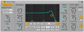
Switch on the External toggle to enable the external sidechain. Once enabled, use the External Source chooser to specify the source of the signal. You can also choose whether the signal should be received Pre FX, Post FX, or Post Mixer via the External Tapping Point chooser.
The Mix slider allows you to use a combination of the external and internal sidechain signals as the envelope follower’s trigger. At 100%, the envelope follower tracks the external sidechain source exclusively. At 0%, only the internal sidechain is used.
You can use the SC Gain control to adjust the level of the external sidechain’s input. Note that the sidechain audio is only a trigger for the envelope follower, so increasing the gain does not increase the volume of the source signal.
To monitor the sidechain signal, enable the Sidechain Listen toggle. This bypasses Auto Filter’s output and lets you hear the sidechain input directly, which can be useful when adjusting sidechain parameters.

The sidechain comes with its own separate frequency-selective filter that you can enable via the SC Filter toggle. When enabled, Auto Filter only reacts to the frequency range specified by the sidechain filter controls.
The Sidechain Filter Frequency control sets the cutoff frequency for the sidechain filter. Use the Type chooser to select a filter from the following: low-shelf, peak, high-shelf, low-pass, band-pass, and high-pass.
The low-shelf filter boosts or attenuates frequencies below the cutoff frequency, while frequencies above remain largely unaffected. Instead of rolling off continuously like a low-pass, the response levels out to a fixed gain set via the Shelf Gain slider. Positive values boost the signal, while negative values attenuate it.
The peak filter boosts or attenuates frequencies around the cutoff frequency, while frequencies above and below that range are progressively less affected. Use the Peak Gain slider to set the amount of boost or attenuation.
The high-shelf filter boosts or attenuates frequencies above the cutoff frequency, while frequencies below the cutoff remain largely unaffected. Like the low-shelf filter, the response flattens out to a constant gain set via the Shelf Gain slider instead of continuing to roll off.
The low-pass filter attenuates frequencies above the cutoff. High-pass allows frequencies above the cutoff frequency to pass while attenuating lower frequencies. Notch attenuates a narrow frequency range while leaving the surrounding frequencies largely unaffected. You can use the Sidechain Filter Q slider to set the filter’s bandwidth.
28.2.7.1 Mono Sidechain
By default, the sidechain signal is converted to mono, and the envelope follower modulation is identical across the left and right channels. You can disable the Mono Sidechain option from the device’s context menu.
28.3 Auto Pan-Tremolo

Auto Pan-Tremolo uses LFO modulation to affect the input signal’s stereo position or amplitude to create automatic panning, tremolo, and gating effects.
There are two modes available: Panning and Tremolo. In Panning mode, two LFOs modulate the placement of the input signal within the stereo panorama by alternating its amplitude between the left and right channels. In Tremolo mode, a single LFO modulates the signal’s amplitude to create variation in volume. Use the respective toggles to switch between modes. The LFO waveform and controls in the display update depending on which mode is selected to reflect its corresponding properties.

The real-time visualization below the LFO waveform shows the current stereo position in Panning mode or the current amplitude level in Tremolo mode. This makes it easy to see at a glance how the input signal is moving across the left and right channels or how its amplitude is fluctuating.
Use the Waveform drop-down to select an LFO shape: Sine, Triangle, Shark Tooth, Saw Up, Saw Down, Square, Random, Wander, and S&H (Sample and Hold).
Select one of the available Time modes to determine the rate of the LFO: Rate, Time, Synced, Dotted, Triplet, or 16th. Once selected, the corresponding modulation rate control below the drop-down updates to reflect the value associated with that mode. For example, in Time mode, you can set the period of the LFO anywhere from 100 milliseconds to 200 seconds, which is useful for creating long modulation cycles.
You can choose between two Stereo Offset modes: Phase and Spin. In Phase mode, the LFO waveforms for the left and right channels can be offset by a set number of degrees. At 180°, the LFOs are perfectly out of phase so that when one LFO reaches its peak value, the other is at its minimum. In Spin mode, the left and right channels diverge progressively based on the set percentage. This adds a subtle asymmetry between the two channels. Note that only Phase mode is available when using the Random, Wander, and S&H waveforms.
When using any of the beat-division-based Time modes (Synced, Triplet, Dotted, or 16th), the Phase Offset control becomes available and can be used to shift the starting point of each LFO channel within its cycle relative to the beat grid. This is useful for offsetting the modulation so that it begins slightly before or after the beat.
When using the Random, Wander, or S&H waveforms, Phase Offset functions as a stereo width control and can be used to introduce variation between the channels.
Use the Invert toggle to flip the polarity of the LFO. When enabled, the positive and negative values of the waveform are swapped, which effectively turns the waveform upside down. In Panning mode, for example, inverting the Saw Up waveform creates a Saw Down waveform. In Tremolo mode, the peaks of the waveform become the valleys and vice versa. When using ramp-shaped waveforms, enabling Invert produces a ducking effect, while disabling it creates a gating effect.
Tremolo mode includes two additional options that can be enabled to influence the behavior of the LFO modulation: Harmonic and Vintage.

With Harmonic enabled, the high and low frequencies are modulated in an alternating pattern rather than in parallel. A fixed crossover of 600 Hz splits the signal into two frequency bands.
With Vintage enabled, the signal’s amplitude is modulated by the LFO as well as shaped by a non-linear curve, which adds warmth and grit to the tremolo effect.
Below the display are controls for adjusting the LFO’s amount, rate, shape, attack, and response to the input signal’s level.

Use the Amount control to set how much LFO modulation is applied to the incoming signal.
The LFO rate can be set using the control to the right of the Amount control. The name and unit of this control change depending on the selected Time mode. For example, the control appears as Freq when Rate is selected and the value is set in hertz (Hz). In Time mode, the control appears as Time and the value is set in milliseconds (ms). In the Synced, Triplet, Dotted, and 16th modes, the control appears as Rate and the value is set in beat divisions.
Note that the values for the Amount control and the LFO rate are shared between the Panning and Tremolo modes and cannot be set independently.
The Shape control affects the LFO waveform differently in each mode. In Panning mode, positive Shape values push each waveform toward its upper and lower limits. This shortens the overlap between the LFOs so that the transition from one channel to the next happens more abruptly. In Tremolo mode, positive values gradually expand the waveform to create rounded peaks, while negative values gradually compress the peaks into an angular shape. At its maximum and minimum values, the Shape control can create ramps for gating effects (with Invert off) and pumping effects (with Invert on).

The Attack Time slider sets how long it takes, in milliseconds, to reach the maximum amount of modulation after a transient is detected. A long attack time can be useful for applying the effect only during the sustained portion of the signal while leaving the initial peaks unaffected. In Panning mode, this keeps transients centered in the stereo field, while in Tremolo mode, this helps preserve their impact.
The Dynamic Frequency Modulation slider determines how much the input signal’s level affects the LFO rate. At positive values, louder signals increase the LFO rate, while negative values decrease it.
28.4 Auto Shift
Auto Shift is a real-time pitch tracking and correction device with controls for vibrato, pitch shifting, and formant shifting. Its design makes it especially well-suited for transforming vocals, though it can be used with any monophonic audio signal. You can pitch correct audio using a defined scale or using the MIDI notes from a separate track. Auto Shift also includes a built-in LFO, so you can modulate incoming audio over time.
28.4.1 Input Section
Auto Shift can receive audio as well as MIDI input. The Input section lets you configure how incoming signals are processed in the device.
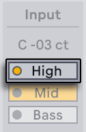
The Input Pitch display shows the pitch of the incoming audio in notes and cents.
You can set the frequency range for the audio input using one of the three Pitch Range toggles. This helps optimize the quality of the pitch estimation and correction. Use High for signals in a high frequency range, Mid for signals in a mid frequency range, and Bass for signals in a low frequency range. Each toggle has an LED that flashes when the incoming audio falls within its corresponding range.
Note that each pitch range setting affects the device’s latency differently, so switching between toggles changes the overall latency.
You can use the Input Gain slider to adjust the gain of the incoming signal from -24 to +24 dB.
The Latency Readout displays the device’s latency in milliseconds. Enabling Live Mode via the toggle in the device’s title bar can help reduce latency, which is particularly useful for live performances. However, slight glitches may occur during note onsets or rapid pitch changes in this mode.
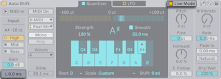
28.4.1.1 MIDI Input
Enabling MIDI input lets you use the notes from a separate MIDI track to pitch correct the incoming audio instead of tuning it to a defined scale via the Quantizer.
The MIDI In toggle shows or hides the MIDI Input panel, which contains track routing and voice mode settings.
Use the MIDI On toggle to activate or deactivate MIDI input. When enabled, the Quantizer tab is replaced with the MIDI tab, where you can further shape the behavior of incoming MIDI notes.
The External Source chooser sets the MIDI sidechain source, i.e., the track used to send notes to Auto Shift. The Tapping Point chooser lets you specify whether the MIDI sidechain is sent before or after any MIDI effects that are in the source track’s device chain. Select Pre FX to bypass the effects on the track, or select Post FX or Post Mixer to include them.
There are two voice mode toggles to choose from: Mono and Poly. Mono uses a single voice, meaning that only one note can be used for the pitch correction at a time. You can use the Glide slider to set the time that overlapping notes take to slide their pitch to the next incoming pitch. Poly can use up to eight voices at once, making it ideal for harmonization. Use the Voice Count chooser to set the maximum number of voices to 2, 4, or 8.
Note that when using MIDI input, Auto Shift will only produce sound when MIDI notes are received.
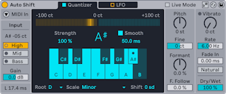
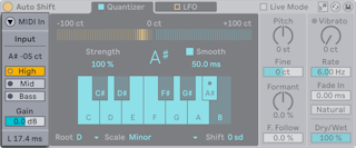
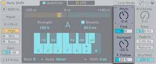
28.4.2 Quantizer Tab
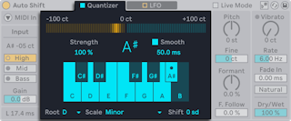
The Quantizer corrects incoming audio according to the notes of a defined scale. In the Quantizer tab, you can access controls for monitoring how the signal is processed, as well as controls for adjusting the correction.
The Pitch Correction Meter displays how much the incoming signal is being shifted in cents to match the target note, which is shown beneath the meter. The target note is determined by the set scale.
You can adjust the intensity of the pitch correction using the Correction Strength slider. The higher the value, the more the audio is shifted to match the target note. Use the Smooth toggle to switch smoothing on or off. When enabled, pitch transitions between notes are smoothed, and more natural vibrato is retained. You can set the smoothing time from 0 to 200 milliseconds using the Smoothing Time slider. The Correction Strength and Smoothing parameters determine the overall style of the pitch correction. With these settings, you can produce results ranging from subtle and nuanced to rigid and quantized.
The Included Notes in Scale display determines which notes are used for the pitch correction. You can create a custom scale by selecting notes in the display, or you can set the key and scale using the Root and Scale choosers. The Pitch Shift slider can be used to transpose the pitch up or down in scale degrees; the pitch shift is applied after the correction.
Auto Shift supports scale awareness: when the Use Current Scale toggle in the device title bar is enabled, the Quantizer follows the clip’s current scale. Additionally, the Included Keys in Scale display highlights the selected scale’s notes in purple, and the Root and Scale choosers are deactivated.
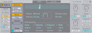
28.4.3 MIDI Tab
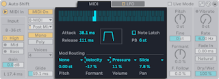
When MIDI input is activated, the Quantizer tab is replaced with the MIDI tab, where you can customize the behavior of incoming MIDI.
The piano visualization displays notes as they are received from the source track. These notes are then used to correct the incoming audio.
Note that scale awareness is not available when using MIDI input. To use the notes within a specific scale, you can add the Scale MIDI effect to the source track. Make sure Auto Shift’s Tapping Point chooser is set to Post FX or Post Mixer so that the effect is included.
The Attack Time slider sets the attack time of the note’s envelope from 0 to 1,000 milliseconds. The Release Time slider sets the release time of the note’s envelope from 0 to 5 seconds.
When the Note Latch toggle is switched on, MIDI notes are held until the next Note On message. The Pitch Bend Range control sets the device’s pitch bend range, from 0 to 48 semitones.
In the Mod Routing section, four parameters can be modulated using MIDI or MPE data: Pitch, Formant, Volume, and Pan. Each parameter can be modulated by one of six modulation sources: Velocity, Pressure, Mod Wheel, Pitch Bend, Note PB, or Slide. Use each target’s dedicated Mod Source drop-down menu to select a modulation source, and adjust the modulation depth with its corresponding Mod Depth slider.
28.4.4 LFO Tab
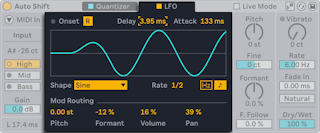
You can use the built-in LFO to apply modulation to the incoming audio’s pitch, formants, volume, and panning.
The LFO Reset toggle switches LFO re-triggering on or off. When enabled, the LFO’s phase will be re-triggered at note onsets. When using the Quantizer, an onset occurs when a pitch is detected after a period of unpitched audio. The Onset Indicator LED flashes when the LFO’s phase is re-triggered. With MIDI input, an onset occurs at the start of a new note, and the Onset Indicator becomes the Trigger Indicator.
The LFO Delay slider sets the delay time before the attack phase begins, from 0 to 1.5 seconds. The LFO Attack slider sets the attack time during which the LFO’s level increases to its peak level, from 0 to 2 seconds. As you modify either value, the waveform in the display will reflect the changes.
You can select from nine modulation waveforms using the LFO Waveform drop-down menu: Sine, Triangle, Triangle 8, Triangle 16, Saw Up, Saw Down, Rectangle, Random, and Random S&H.
The LFO Rate slider lets you select the speed of the LFO in milliseconds or tempo-synced beat divisions, as determined by the LFO Sync toggles.
In the Mod Routing section, you can modulate four parameters using the LFO: Pitch, Formant, Volume, and Pan. The individual Mod Depth sliders set the amount of modulation that is applied to each parameter.
Note that the LFO modulation affects the incoming signal regardless of whether it is being pitch-corrected.
28.4.5 Pitch Section
You can apply both pitch and formant shifting to incoming signals using the controls in the Pitch section.
The Pitch Shift control sets the amount of transposition applied in semitones. You can use the Pitch Shift Fine slider to set the transposition in cents.
Use the Formant Shift control to shift the formants — the resonant frequencies that help define the tonal characteristics of a sound — within a range of -100% to 100%. At higher values, pitches will sound higher and more resonant, while at lower values pitches will sound lower and less full. Shifting formants lets you create a higher or lower sound without actually transposing the pitch.
The Formant Follow slider determines how much of the formant shifting follows the pitch shifting; higher values result in a more natural-sounding transposition.
Note that you can use the Pitch Shift and Formant Shift controls with or without pitch correcting the signal.
28.4.6 Vibrato Section
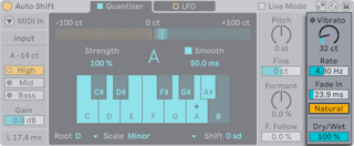
The Vibrato section contains controls for applying vibrato to incoming audio and adjusting the overall balance of the dry and processed signal.
There are three main vibrato controls:
- Vibrato Amount — adjusts the depth of the vibrato, from 0 to 200 cents.
- Vibrato Rate — adjusts the speed of the vibrato, from 2 to 15 Hz.
- Vibrato Fade In — adjusts the vibrato’s fade-in time in milliseconds.
Enabling the Natural Vibrato toggle creates variations in the vibrato’s speed and depth, producing a more realistic effect.
Note that you can use the vibrato controls with or without pitch correcting the signal.
The Dry/Wet slider sets the balance between the dry and processed signals. At 0%, no pitch correction is applied, while at 100%, only the pitch corrected signal is heard. You can create a doubler effect by setting this value to 50%, which equally balances the original and corrected signals.
28.5 Beat Repeat
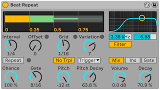
Beat Repeat allows for the creation of controlled or randomized repetitions of an incoming signal.
The Interval control defines how often Beat Repeat captures new material and begins repeating it. Interval is synced to and set in terms of the song tempo, with values ranging from ”1/32” to ”4 Bars.” The Offset control shifts the point defined by Interval forward in time. If Interval is set to ”1 Bar,” for example, and Offset to ”8/16”, material will be captured for repetition once per bar on the third beat (i.e., halfway, or eight-sixteenths of the way, through the bar).
You can add randomness to the process using the Chance control, which defines the likelihood of repetitions actually taking place when Interval and Offset ”ask” for them. If Chance is set to 100 percent, repetitions will always take place at the given Interval/Offset time; if set to zero, there will be no repetitions.
Gate defines the total length of all repetitions in sixteenth notes. If Gate is set to ”4/16”, the repetitions will occur over the period of one beat, starting at the position defined by Interval and Offset.
Activating the Repeat button bypasses all of the above controls, immediately capturing material and repeating it until deactivated.
The Grid control defines the grid size — the size of each repeated slice. If set to ”1/16”, a slice the size of one sixteenth note will be captured and repeated for the given Gate length (or until Repeat is deactivated). Large grid values create rhythmic loops, while small values create sonic artifacts. The No Triplets button sets grid division as binary.
Grid size can be changed randomly using the Variation control. If Variation is set to ”0”, grid size is fixed. But when Variation is set to higher values, the grid fluctuates considerably around the set Grid value. Variation has several different modes, available in the chooser below: Trigger creates variations of the grid when repetitions are triggered; 1/4, 1/8 and 1/16 trigger variations in regular intervals; and Auto forces Beat Repeat to apply a new random variation after each repetition — the most complex form of grid variation in Beat Repeat (especially if triplets are also allowed).
Beat Repeat’s repetitions can be pitched down for special sonic effects. Pitch is adjusted through resampling in Beat Repeat, lengthening segments to pitch them down without again compressing them to adjust for the length change. This means that the rhythmical structure can become quite ambiguous with higher Pitch values. The Pitch Decay control tapers the pitch curve, making each repeated slice play lower than the previous one. Warning: This is the most obscure parameter of Beat Repeat.
Beat Repeat includes a combined low-pass and high-pass filter for defining the passed frequency range of the device. You can turn the filter on and off, and set the center frequency and width of the passed frequency band, using the respective controls.
The original signal (which was received at Beat Repeat’s input) is mixed with Beat Repeat’s repetitions according to one of three mix modes: Mix allows the original signal to pass through the device and have repetitions added to it; Insert mutes the original signal when repetitions are playing but passes it otherwise; and Gate passes only the repetitions, never passing the original signal. Gate mode is especially useful when the effect is housed in a return track.
You can set the output level of the device using the Volume control, and apply Decay to create gradually fading repetitions.
28.6 Cabinet
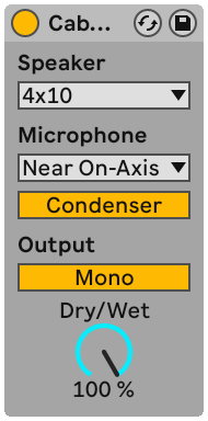
Cabinet is an effect that emulates the sound of five classic guitar cabinets. Developed in collaboration with Softube, Cabinet uses physical modelling technology to provide a range of authentic sounds, with optimized mics and mic positioning.
The Speaker chooser allows you to select from a variety of speaker sizes and combinations. The chooser’s entries indicate the number of speakers and the speaker size in inches. For example, ”4x12” means four 12-inch speakers. In the real world, more and larger speakers generally means higher volumes.
The Microphone chooser changes the position of the virtual microphone in relation to the speaker cabinet. Near On-Axis micing results in a bright, focused sound, while Near Off-Axis is more resonant and a bit less bright. Choose the Far position for a balanced sound that also has some characteristics of the virtual ”room.”
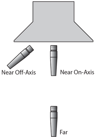
The switch below the Microphone chooser toggles between a Dynamic and Condenser mic. Dynamic mics are a bit grittier and commonly used when close-micing guitar cabinets because they are capable of handling much higher volumes. Condenser mics are more accurate, and are commonly used for micing from a distance. Of course, Cabinet’s virtual condenser mic won’t be damaged by high volume levels, so feel free to experiment.
The Output switch toggles between mono and stereo (Dual) processing. Note that in Dual mode, Cabinet uses twice as much CPU.
The Dry/Wet control adjusts the balance between the processed and dry signals.
28.6.1 Cabinet Tips
Here are some tips for using Cabinet:
28.6.1.1 Amps and Cabinets
Guitar cabinets are normally fed by guitar amps. For this reason, Cabinet is paired with Amp, and the two are normally used together. But you can also achieve interesting and exotic sounds by using Amp and Cabinet separately.
28.6.1.2 Multiple mics
A common studio technique is to use multiple mics on a single cabinet, and then adjust the balance during mixing. This is easy to do by using Live’s Audio Effect Racks. Try this:
- Configure one instance of Cabinet as you like.
- Put the Cabinet into an Audio Effect Rack.
- Duplicate the Rack chain that contains the original Cabinet as many times as you like.
- In the additional chains, choose a different Microphone setting and/or mic type.
- Adjust the relative volumes of the Rack’s chains in the Rack’s mixer.
28.7 Channel EQ
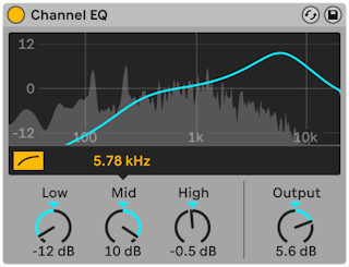
Inspired by EQs found on classic mixing desks, Channel EQ is a simple, yet flexible three-band EQ, fine-tuned to provide musical results for a variety of audio material.
Activating the HP 80 Hz switch will toggle a high-pass filter, which is useful for removing the rumble from a signal.
The Low parameter controls the gain of a low shelf filter, tuned to 100 Hz. This filter can boost or attenuate low frequencies by a range of +/- 15 dB. The filter curve is adaptive and will change dynamically relative to the amount of gain applied.
The Mid parameter controls the gain of a sweepable peak filter. Unlike the Low and High parameters, Mid has a range of +/- 12 dB. The frequency slider located above the Mid control allows you to set the center frequency of this filter from 120 Hz to 7.5 kHz.
When boosting, the High parameter controls the gain of a high shelf filter, up to 15 dB. When attenuating, the shelving filter is combined with a low-pass filter. Turning the parameter from 0 dB towards -15 dB will simultaneously reduce the cutoff frequency of the low-pass filter from 20 kHz to 8 kHz.
A spectrum visualization provides real-time visual feedback of the resulting filter curves and processed signal.
The Output control sets the amount of gain applied to the processed signal, and can be used to compensate for any changed signal amplitude resulting from the EQ settings.
28.7.1 Channel EQ Tips
You can use Channel EQ to further shape the output of a reverb effect in a device chain.
You can also shape the sound of a single drum or an entire drum kit, by placing an instance of Channel EQ onto one or multiple Drum Rack pads.
Adding an instance of Saturator after Channel EQ in a device chain allows you to simulate the analog nonlinearities of a mixer channel strip. In such cases, boosting the low end considerably would also lead to increased distortion, similar to the behavior of analog mixing desks.
28.8 Chorus-Ensemble
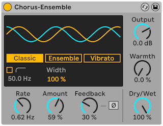
Chorus-Ensemble offers a classic two-delay line chorus with an optional third delay line mode. With a wide variety of tools for thickening sounds, creating flanging and vibrato effects, this device also allows you to easily recreate string ensemble chorus sounds.
Three different modes are provided, which can be chosen in the display: Classic, Ensemble, and Vibrato.
Classic mode creates a thickened sound by adding two time-modulated delayed signals to the input. Use it for a classic chorus sound, adding light motion to your audio signal.
Ensemble mode is inspired by a thick three-delay line chorus pedal used in the ‘70s. Ensemble mode is based on and shares controls with Classic mode, but creates richer, smoother, and more intense chorus sound by using three delayed signals with evenly split modulation phase offsets.
Vibrato mode applies stronger modulation than a chorus to create pitch variation. The shape of the modulation waveform can morph seamlessly from a sine to a triangle, and be used to create well-known “police siren” sounds.
In addition to the mode selector buttons, the display also provides access to a high-pass filter and the Width parameter. Width is active in Classic and Ensemble modes, but while in Vibrato mode, this parameter is replaced by Offset and Shape controls.
When enabled, the high-pass filter reduces the chorus effect on signal components below the frequency set by the High-Pass Frequency slider, ranging from 20 Hz to 2000 Hz.
Width sets the stereo width of the wet signal, which in turn adjusts the chorus level balance between the mid and side channels. At 0% the signal will be mono, at 100% the balance is equal, and at 200% the chorus level is twice as loud in the sides as in the middle. This is used for maintaining the level of the effect across the stereo field, which can be helpful during mixing.
When using Vibrato mode, Offset adjusts the amount of phase offset between the waveforms for the left and right channel. At 180°, the channels will be perfectly out of phase. Shape enables you to change the shape of the modulation waveform between a sine and a triangle.
Global parameters available include Rate, Amount, Feedback, Output, Warmth and Dry/Wet.
Rate sets the modulation rate in Hertz, and can be adjusted either with the dial or by dragging up or down in the display. Turn up Rate for a more drastic chorus sound, or keep it low for more gentle phasing.
Amount adjusts the amplitude of the modulation signals that affects delay times. Higher values result in a stronger time deviation from the unmodulated time setting.
Feedback sets the amount of each channel’s output that is fed back to its input. Increasing this sounds more extreme and tends to increase upper harmonic material, and will also create audible delays if playback is stopped. The feedback signal can be inverted using the Ø button, which results in a “hollow” sound when combined with high feedback values.
Output sets the amount of gain applied to the processed signal.
Warmth adds slight distortion and filtering for a warmer sound. Turn it up for more crunch!
Dry/Wet adjusts the balance between the processed and dry signals. Set it to 100% when using Chorus-Ensemble in a return track. Note that this is disabled in Vibrato mode.
28.8.1 Chorus-Ensemble Tips
Here are some tips for using Chorus-Ensemble:
- Use Ensemble mode at a rate between 1 Hz and 1.8 Hz and 100% Amount on dry guitars to create a typical surf-rock sound.
- Automate the Feedback Invert toggle at Feedback levels > 90% to create massive bursts of decaying oscillations.
28.9 Compressor
A compressor reduces gain for signals above a user-settable threshold. Compression reduces the levels of peaks, opening up more headroom and allowing the overall signal level to be turned up. This gives the signal a higher average level, resulting in a sound that is subjectively louder and ”punchier” than an uncompressed signal.
A compressor’s two most important parameters are the Threshold and the compression Ratio.
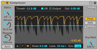
The Threshold slider sets where compression begins. Signals above the threshold are attenuated by an amount specified by the Ratio parameter, which sets the ratio between the input and output signal. For example, with a compression ratio of 3, if a signal above the threshold increases by 3 dB, the compressor output will increase by only 1 dB. If a signal above the threshold increases by 6 dB, then the output will increase by only 2 dB. A ratio of 1 means no compression, regardless of the threshold.
The orange Gain Reduction meter shows how much the gain is being reduced at any given moment. The more reduction, the more audible the effect; a gain reduction above 6 dB or so might produce the desired loudness, but significantly alters the sound and is easily capable of destroying its dynamic structure. This is something that cannot be undone in later production steps. Keep this in mind especially when using a compressor, limiter, or sound loudness-maximizing tool in the Main track. Less is often more here.
Because compression reduces the volume of loud signals and opens up headroom, you can use the Output (Out) control so that the peaks once again hit the maximum available headroom. The Output meter shows the output signal’s level. Enabling the Makeup button automatically compensates the output level if the threshold and ratio settings change.
Dry/Wet adjusts the balance between the compressed and uncompressed signals. At 100%, only the compressed signal is heard, while at 0%, the device is effectively bypassed.
The Knee control adjusts how gradually or abruptly compression occurs as the threshold is approached. With a setting of 0 dB, no compression is applied to signals below the threshold, and full compression is applied to any signal at or above the threshold. With very high ratios, this so-called ”hard knee” behavior can sound harsh. With higher (or ”soft”) knee values, the compressor begins compressing gradually as the threshold is approached. For example, with a 10 dB knee and a -20 dB threshold, subtle compression will begin at -30 dB and increase so that signals at -10 dB will be fully compressed.
Compressor’s display can be switched between several modes via switches in the bottom corners of the display:
- The Collapsed view shows only the essential controls.
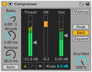
- The Transfer Curve shows the input level on the horizontal axis and output level vertically. This view is useful for setting the Knee parameter, which is visible as a pair of dotted lines around the threshold.
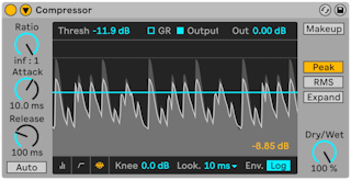
- The Activity view shows the level of the input signal in light gray. In this mode, the GR and Output switches toggle between showing the amount of gain reduction in orange or the output level in a darker gray. These views are useful for visualizing what’s happening to the signal over time.
The Attack and Release controls are essential parameters for controlling the response time of Compressor by defining how fast it reacts to input-level changes.
Attack defines how long it takes to reach maximum compression once a signal exceeds the threshold, while Release sets how long it takes for the compressor to return to normal operation after the signal falls below the threshold. With Auto Release enabled, the release time will adjust automatically based on the incoming audio.
A slight amount of attack time (10-50 ms) allows peaks to come through unprocessed, which helps preserve dynamics by accentuating the initial portion of the signal. If these peaks cause overloads, you can try shortening the attack time, but extremely short times take the ”life” out of the signal, and may lead to a slight “buzziness” caused by distortion. Short release times can cause ”pumping” as the compressor tries to figure out whether to compress or not; while generally considered an undesirable effect, some engineers use it on full drum kits to give unusual ”sucking” effects. Careful adjustment of attack and release times is essential when it comes to compression of rhythmical sources. If you are not used to working with compressors, play a drum loop and spend some time adjusting Attack, Release, Threshold and Gain. It can be very exciting!
A compressor can only react to an input signal once it occurs. Since it also needs to apply an attack/release envelope, the compression is always a bit too late. A digital compressor can solve this problem by simply delaying the input signal a little bit. Compressor offers three different Lookahead times: zero ms, one ms and ten ms. The results may sound pretty different depending on this setting.
Compressor can be switched between three basic modes of operation. With Peak selected, Compressor reacts to short peaks within a signal. This mode is more aggressive and precise, and so works well for limiting tasks where you need to ensure that there are absolutely no signals over the set threshold. RMS mode causes Compressor to be less sensitive to very short peaks and compress only when the incoming level has exceeded the threshold for a slightly longer time. RMS is closer to how people actually perceive loudness and is usually considered more musical. Expand mode lets you set the ratio of expansion between the input and output level. For example, a ratio of 1 to 2 means that for every 1 dB of input above the threshold level, the output level will increase by 2 dB. A ratio of 1 to 1 results in no expansion. For more information about the various types of dynamics processing, see the Multiband Dynamics section.
In addition to these modes, Compressor can be switched between two envelope follower shapes that offer further options for how the device measures and responds to signal levels. In linear (Lin) mode, the speed of the compression response is determined entirely by the Attack and Release values. In logarithmic (Log) mode, sharply compressed peaks will have a faster release time than less compressed material. This can result in smoother and less noticeable compression than Lin mode. Note that the Lin/Log switch is not visible in Compressor’s collapsed view.
28.9.1 Sidechain Parameters
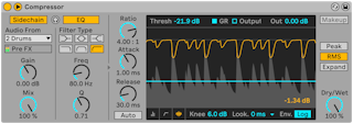
Normally, the signal being compressed and the input source that triggers the compressor are the same signal. But by using sidechaining, it is possible to compress a signal based on the level of another signal or a specific frequency component. To access the Sidechain parameters, unfold the Compressor window by toggling the  button in its title bar.
The sidechain parameters are divided into two sections. On the left are the external controls. Enabling this section with the Sidechain button allows you to select any of Live’s internal routing points from the choosers below. This causes the selected source to act as the compressor’s trigger, instead of the signal that is actually being compressed.
The Gain knob adjusts the level of the external sidechain’s input, while the Dry/Wet knob allows you to use a combination of sidechain and original signal as the compressor’s trigger. With Dry/Wet at 100%, the compressor is triggered entirely by the sidechain source. At 0%, the sidechain is effectively bypassed. Note that increasing the gain does not increase the volume of the source signal in the mix. The sidechain audio is only a trigger for the compressor and is never actually heard.
Note that automatic Makeup is not available when using external sidechain.
On the right of the external section are the controls for the sidechain EQ. Enabling this section causes the compressor to be triggered by a specific band of frequencies, instead of a complete signal. These can either be frequencies in the compressed signal or, by using the EQ in conjunction with an external sidechain, frequencies in another track’s audio.
The headphones button between the external and EQ sections allows you to listen to only the sidechain input, bypassing the compressor’s output. Since the sidechain audio isn’t fed to the output, and is only a trigger for the compressor, this temporary listening option can make it much easier to set sidechain parameters and hear what’s actually making the compressor work.
28.9.2 Compressor Tips
This section presents some tips for using Compressor effectively, particularly with the sidechain options.
28.9.2.1 Mixing a Voiceover
Sidechaining is commonly used for so-called ”ducking” effects. For example, imagine that you have one track containing a voiceover and another track containing background music. Since you want the voiceover to always be the loudest source in the mix, the background music must get out of the way every time the narrator is speaking. To do this automatically, insert a Compressor on the music track, but select the narration track’s output as the external sidechain source.
28.9.2.2 Sidechaining in Dance Music
Sidechaining/ducking is a dance music producer’s secret weapon because it can help to ensure that basslines (or even whole mixes) always make room for the kick drum. By inserting a compressor on the bass (or Main) track and using the kick drum’s track as the sidechain input, you can help to control problematic low frequencies that might interfere with the kick drum’s attack.
Using the sidechain EQ in conjunction with this technique can create ducking effects even if you only have a mixed drum track to work with (as opposed to an isolated kick drum). In this case, insert the Compressor on the track you want to duck. Then choose the drum track as the external sidechain source. Then enable the sidechain EQ and select the low-pass filter. By carefully adjusting the Frequency and Q settings, you should be able to isolate the kick drum from the rest of the drum mix. Using the sidechain listen mode can help you tune the EQ until you find settings you’re happy with.
Note that Compressor’s internal algorithms were updated in Live 9, in collaboration with Dr. Joshua D. Reiss of the Centre for Digital Music, Queen Mary University of London.
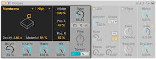
28.10 Corpus
Corpus is an effect that simulates the acoustic characteristics of seven types of resonant objects. Developed in collaboration with Applied Acoustics Systems, Corpus uses physical modeling technology to provide a wide range of parameters and modulation options.
28.10.1 Resonator Parameters
The Resonance Type chooser allows you to select from seven types of physically modeled resonant objects:
- Beam simulates the resonance properties of beams of different materials and sizes.
- Marimba, a specialized variant of the Beam model, reproduces the characteristic tuning of marimba bar overtones which are produced as a result of the deep arch-cut of the bars.
- String simulates the sound produced by strings of different materials and sizes.
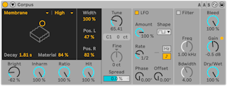
- Membrane is a model of a rectangular membrane (such as a drum head) with a variable size and construction.
- Plate simulates sound production by a rectangular plate (a flat surface) of different materials and sizes.
- Pipe simulates a cylindrical tube that is fully open at one end and has a variable opening at the other (adjusted with the Opening parameter).
- Tube simulates a cylindrical tube that is fully open at both ends.
The Resonator Quality chooser controls the trade-off between the sound quality of the resonators and performance by reducing the number of overtones that are calculated. Eco uses minimal CPU resources, while High creates more sophisticated resonances. This parameter is not used with the Pipe or Tube resonators.
The Decay slider adjusts the amount of internal damping in the resonator, and thus the decay time.
The Material slider adjusts the variation of the damping at different frequencies. At lower values, low frequency components decay slower than high frequency components (which simulates objects made of wood, nylon or rubber). At higher values, high frequency components decay slower (which simulates objects made of glass or metal). This parameter is not used with the Pipe or Tube resonators.
The Radius slider is only available for the Pipe and Tube resonators, and appears in place of the Material parameter mentioned above. Radius adjusts the radius of the pipe or tube. As the radius increases, the decay time and high frequency sustain both increase. At very large sizes, the fundamental pitch of the resonator also changes.
The Decay and Material/Radius parameters can also be controlled with the X-Y controller.
The Bright knob adjusts the amplitude of various frequency components. At higher values, higher frequencies are louder. This parameter is not used with the Pipe or Tube resonators.
Inharm (Inharmonics) adjusts the pitch of the resonator’s harmonics. At negative values, frequencies are compressed, increasing the number of lower partials. At positive values, frequencies are stretched, increasing the number of upper partials. This parameter is not used with the Pipe or Tube resonators.
Opening, which is only available for the Pipe resonator, scales between an open and closed pipe. At 0%, the pipe is fully closed on one side, while at 100% the pipe is open at both ends.
Ratio, which is only available for the Membrane and Plate resonators, adjusts the ratio of the membrane/plate along its x and y axes.
The Hit knob adjusts the location on the resonator at which the object is struck or otherwise activated. At 0%, the object is hit at its center. Higher values move the activation point closer to the edge. This parameter is not used with the Pipe or Tube resonators.
The Width slider adjusts the stereo mix between the left and right resonators. At 0%, both resonators are fed equally to each side, resulting in mono output. At 100%, each resonator is sent exclusively to one channel.
The Pos. L and Pos. R controls adjust the location on the left and right resonator where the vibrations are measured. At 0%, the resonance is monitored at the object’s center. Higher values move the listening point closer to the edge. These parameters are not used with the Pipe or Tube resonators, which are always measured in the middle of their permanently open end.
The Tune knob adjusts the frequency of the resonator in Hertz. When MIDI Frequency is enabled in Corpus’s Sidechain section, the knob can be used to adjust the coarse tuning of the MIDI modulation.
The Fine knob allows for fine tuning MIDI modulation in cents when sidechain MIDI Frequency is enabled.
Spread detunes the two resonators in relation to each other. Positive values raise the pitch of the left resonator while lowering the pitch of the right one, while negative values do the opposite. At 0%, the resonators are tuned the same.
28.10.2 LFO Section
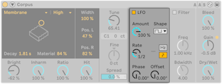
Corpus contains a Low Frequency Oscillator (LFO) to modulate the resonant frequency. The Amount control sets how much the LFO affects the frequency.
The Rate control specifies the LFO speed. It can be set in terms of Hertz, or synced to the song tempo, allowing for controlled rhythmic modulation.
Available LFO waveform shapes are sine (creates smooth modulations with rounded peaks and valleys), square, triangle, sawtooth up, sawtooth down and two types of noise (stepped and smooth).
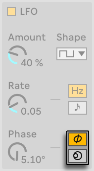
Although only one set of LFO controls is visible, there are actually two LFOs, one for each stereo channel. The Phase and Spin controls define the relationship between these two LFOs.
Phase keeps both LFOs at the same frequency, but can set the two LFO waveforms ”out of phase” with each other, creating stereo movement. When set to 180, the LFO outputs are 180 degrees apart, so that when one LFO reaches its peak, the other is at its minimum. With Phase set to 360 or 0 the two LFOs run in sync.
When the LFOs are synced to song tempo, an additional Offset knob is available, which shifts the start point of the LFO along its waveform.
Spin (only available when the LFOs are in Hertz mode) detunes the two LFO speeds relative to each other. Each stereo channel is modulated at a different frequency, as determined by the Spin amount.
Phase or Spin can be chosen when the LFOs are in Hertz mode using the LFO Stereo mode icons.
For the noise waveforms, the Phase and Spin controls are not relevant and do not affect the sound.
28.10.3 Filter Section
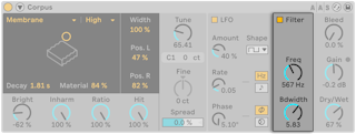
The processed signal can be fed through a band-pass filter that can be toggled on or off with the Filter switch.
The Freq knob adjusts the center frequency of the filter while Bdwidth adjusts the bandwidth of the filter.
28.10.4 Global Parameters
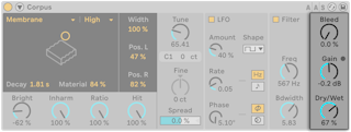
Bleed mixes a portion of the unprocessed signal with the resonated signal. At higher values, more of the original signal is applied. This is useful for restoring high frequencies, which can often be damped when the tuning or quality are set to low values. This parameter is deactivated with the Pipe or Tube resonators.
Gain boosts or attenuates the level of the processed signal. Corpus contains a built-in limiter that automatically activates when the audio level is too high. This is indicated by the LED next to the Gain knob.
The Dry/Wet control adjusts the balance between the dry input signal and the signal sent to Corpus’s processing. Turning Dry/Wet down will not cut resonances that are currently sounding, but rather stop new input signals from being processed.
28.10.5 Sidechain Parameters
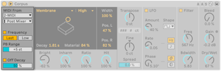
The frequency and/or decay rate of the resonance can be MIDI-modulated by enabling the Frequency and/or Off Decay switches in the Sidechain section. Toggle the  button in Corpus’s title bar to access Sidechain parameters. This button will light up if the sidechain is active.
The MIDI From choosers allow you to select the MIDI track and tapping point from which to receive MIDI note information.
With Frequency enabled, the tuning of the resonance is determined by the incoming MIDI note. If multiple notes are held simultaneously, the Last/Low switch determines whether the last or the lowest note will have priority. The Transpose and Fine knobs in the Resonator section allow for coarse and fine offset of the MIDI-modulated tuning. PB Range sets the range in semitones of pitch bend modulation.
With Frequency deactivated, the Tune control in the Resonator section adjusts the base frequency of the resonance in Hertz. The corresponding MIDI note number and fine tuning offset in cents is displayed below.
Enabling Off Decay causes MIDI Note Off messages to mute the resonance. The slider below the switch determines the extent to which MIDI Note Off messages mute the resonance. At 0%, Note Offs are ignored, and the decay time is based only on the value of the Decay parameter, which can be adjusted using the X-Y controller or Decay slider. This is similar to how real-world mallet instruments such as marimbas and glockenspiels behave. At 100%, the resonance is muted immediately at Note Off, regardless of the Decay time.
28.11 Delay
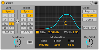
The Delay provides two independent delay lines, one for each channel (left and right).
To refer delay time to the song tempo, activate the Sync switch, which allows using the Delay Time beat division chooser. The numbered switches represent time delay in 16th notes. For example, selecting ”4” delays the signal by four 16th notes, which equals one beat (a quarter note) of delay.
If the Sync switch is off, the delay time reverts to milliseconds. In this case, to edit the delay time, click and drag up the Delay Time knob.
With Stereo Link engaged, the left channel’s settings are applied to the right channel, and changing either channel’s Sync switch or Delay Time settings will apply the changes to both sides.
The Feedback parameter defines how much of each channel’s output signal feeds back into the delay lines’ inputs. Internally, they are two independent feedback loops, so a signal on the left channel does not feed back into the right channel and vice versa.
The  button will cause the delay to endlessly cycle the audio which is in its buffer at the moment that the button is pressed, ignoring any new input until Freeze is disabled.
The delay is preceded by a band-pass filter that can be toggled on and off with a switch, and controlled with an X-Y controller. To define the filter bandwidth, click and drag on the vertical axis. To set the position of the frequency band, click and drag on the horizontal axis.
Filter frequency and delay time can be modulated by an LFO, making it possible to achieve a range of sounds from light chorus-like effects through to heavy contorted noise. The Rate slider sets the frequency of the modulation oscillator in Hertz. The Filter slider adjusts the amount of modulation that is applied to the filter, and the Time slider adjusts the amount of modulation that is applied to the delay time.
Changing the delay time while Delay is processing audio can cause abrupt changes in the sound of the delayed signal. You can choose between three delay transition modes:
- Repitch causes a pitch variation when changing the delay time, similar to the behavior of old tape delay units. Repitch mode is the default option.
- Fade creates a crossfade between the old and new delay times. This sounds a bit similar to time stretching if the delay time is gradually changed.
- Jump immediately jumps to the new delay time. Note that this will cause an audible click if the delay time is changed while delays are sounding.
Tip: Try using the Time slider to explore the effect of time modulation on the different transition modes.
When the Ping Pong switch is activated, the signal jumps from the left to the right output.
The Dry/Wet control adjusts the balance between the processed and dry signals. Set it to 100 percent when using Delay in a return track. The Dry/Wet parameter’s context menu lets you toggle Equal-Loudness. When enabled, a 50/50 mix will sound equally loud for most signals.
Sets saved in versions of Live older than Live 10.1 that used Simple Delay or Ping Pong Delay devices will show an Upgrade button in the title bar of each instance of Delay when loading the Set. Upgrading the device will preserve the previously used device’s free delay time range, and will only affect the sound of the Set or preset if the free delay time parameter was either mapped to a Macro Control or to a Max for Live device.
28.11.1 Delay Tips
28.11.1.1 Glitch Effect
Enable the Stereo Link switch and set the delay time to around 400-500ms. Dial the Feedback to 80% or above. Disable the band-pass filter, adjust the Filter slider to 0%, and set the Time slider to 100%. Select the Fade transition mode and make sure Ping Pong is disabled. Set the Dry/Wet control to 80% or above.
28.11.1.2 Chorus Effect
Disable the Stereo Link switch, set the left channel’s delay time to 12ms, and adjust the right channel’s delay time to 17ms. Dial the Feedback to 60%. Enable the band-pass filter, set the Filter Frequency to 750 Hz, and adjust the Width slider to 6.5. Set the Rate slider to 5 Hz, bring the Filter slider to 10%, and dial the Time slider to 12%. Select the Repitch transition mode and enable the Ping Pong switch.
28.12 Drum Buss
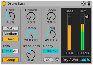
Drum Buss is an analog-style drum processor that was designed to add body and character to a group of drums, while gluing them together in a tight mix.
The Trim slider lets you reduce the input level before any processing is applied to the signal.
The Comp toggle applies a fixed compressor to the input signal before it is processed by the distortion. The compressor is optimized for balancing out groups of drums, with fast attack, medium release and moderate ratio settings, as well as ample makeup gain.
There are three types of distortion which can be applied to the input signal. Each distortion type adds an increasing degree of distortion, while lending its own character to the overall sound:
- Soft: waveshaping distortion
- Medium: limiting distortion
- Hard: clipping distortion with bass boost
For more intensity, it is possible to drive the input prior to distorting it. The Drive control lets you determine how much drive is applied to the input signal.
Drum Buss combines commonly-used drum processing tools for shaping the mid-high range and filling out the low end, which we will look at in the following sections.
28.12.0.1 Mid-High Frequency Shaping
The mid-high frequency shaping tools are designed to add clarity and presence to drums such as snares and hi-hats.
Crunch adjusts the amount of sine-shaped distortion applied to mid-high frequencies.
The Damp control is a low-pass filter, which removes unwanted high frequencies that can occur after adding distortion.
The Transients knob emphasizes or de-emphasizes the transients of frequencies above 100 Hz. Positive values add attack and increase sustain, resulting in a full, “punchy” sound. Negative values also add attack, but decrease sustain. This tightens up the drums, giving them a sharper, more crisp sound with less room and rattle.
28.12.0.2 Low-End Enhancement
Drum Buss’s low-end enhancement is made up of two tools: a resonant filter, which dramatically boosts bass frequencies, as well as a Decay control, which allows you to adjust the decay rate of both the incoming audio and the signal processed by the resonant filter. These tools help you to fill out the low-end of your drums.
The Boom knob adjusts the amount of low-end enhancement that the resonant filter produces. The Bass Meter lets you see the Boom’s effect on the signal, which can be particularly useful if you can’t hear it.
The Freq knob adjusts the frequency of the low-end enhancer. Force To Note lets you tune the low-end enhancer by setting its frequency to the value of the nearest MIDI note.
The Decay control adjusts the decay rate of the low frequencies. When the Boom amount is set to 0%, the decay affects the incoming (post-drive and distortion) signal only. When the “Boom Level” is adjusted above 0%, the decay affects both the incoming and processed signals.
To solo the result of the low-frequency enhancer, enable Boom Audition via the headphone icon.
28.12.0.3 Output
The Dry/Wet control adjusts the balance between the processed and dry signals.
The Output Gain slider sets the amount of gain applied to the processed signal.
28.13 Dynamic Tube
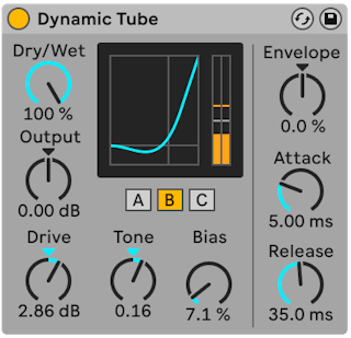
The Dynamic Tube effect infuses sounds with the peculiarities of tube saturation. An integrated envelope follower generates dynamic tonal variations related to the level of the input signal.
Three tube models, A, B and C, provide a range of distortion characteristics known from real amplifier tubes. Tube A does not produce distortions if Bias is set low, but will kick in whenever the input signal exceeds a certain threshold, creating bright harmonics. Tube C is a very poor tube amp that produces distortions all the time. The qualities of Tube B lie somewhere between these two extremes.
The Tone control sets the spectral distribution of the distortions, directing them into the higher registers, or through the midrange and deeper.
The Drive control determines how much signal reaches the tube; greater Drive yields a dirtier output. The intensity of the tube is controlled by the Bias dial, which pushes the signal into the celebrated realms of nonlinear distortion. With very high amounts of Bias, the signal will really start to break apart.
The Bias parameter can be positively or negatively modulated by an envelope follower, which is controlled with the Envelope knob. The more deeply the envelope is applied, the more the Bias point will be influenced by the level of the input signal. Negative Envelope values create expansion effects by reducing distortion on loud signals, while positive values will make loud sounds dirtier.
Attack and Release are envelope characteristics that define how quickly the envelope reacts to volume changes in the input signal. Together, they shape the dynamic nature of the distortions. Note that if Envelope is set to zero, they will have no effect.
Cut or boost the device’s final signal level with the Output dial.
Aliasing can be reduced by enabling Hi-Quality mode, which can be accessed via the device title bar’s context menu. This improves the sound quality, particularly with high frequency signals, but there is a slight increase in CPU usage.
28.14 Echo
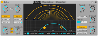
Echo is a modulation delay effect that lets you set the delay time on two independent delay lines, while giving you control over envelope and filter modulation.
The Channel Mode buttons let you choose between three different modes: Stereo, Ping Pong and Mid/Side.
The Left and Right delay line controls let you choose the delay time, which can be set in beat divisions or milliseconds, depending on the state of the Sync switch. Note that when the Mid/Side channel mode is selected, the Left and Right delay line controls are replaced with Mid and Side knobs.
You can use the Sync Mode choosers to select one of the following beat-synced modes: Notes, Triplet, Dotted and 16th. Note that when switching between Sync Modes, the resulting changes are only audible while the Sync switch is set to Sync.
When Stereo Link is engaged, changing either channel’s delay line control, Sync switch or Sync Mode settings will apply the changes to both sides.
Changing the Delay Offset sliders shortens or extends the delay time by fractional amounts, thus producing the ”swing” type of timing effect found in drum machines. Note that when Stereo Link is enabled, the Delay Offset can still be adjusted individually for the two delay lines.
The Input knob sets the amount of gain applied to the dry signal. To apply distortion to the dry signal, press the “D” button.
The Feedback parameter defines how much of each channel’s output signal feeds back into the delay lines’ inputs. The “Ø“ button inverts each channel’s output signal before adding it back to their inputs.
28.14.1 Echo Tab
The Echo tab provides a visualization and control of the delay lines and filter parameters.
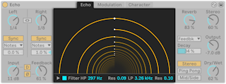
The Echo Tunnel’s circular lines represent the individual repeats, progressing from the outside of the tunnel to its center. The distance between the lines indicates the time between the repeats, and the white dots in the middle form a fixed 1/8th note grid for reference. You can adjust the delay times for each delay line by clicking and dragging in the display.
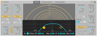
The Filter toggle enables a high-pass and low-pass filter. The HP slider adjusts the cutoff frequency of the high-pass filter and the adjacent Res slider adjusts the high-pass filter’s resonance. The LP slider adjusts the cutoff frequency of the low-pass filter, and you can use the Res slider on the right side to adjust the low-pass filter’s resonance.
The Filter Display makes it possible to visualize the filter curves. To show or hide the Filter Display, use the triangular toggle button. You can also adjust the filter parameters by clicking and dragging either of the filter dots in the Filter Display.
28.14.2 Modulation Tab
Echo’s Modulation tab contains an LFO that modulates filter frequency and delay time, and an envelope follower that can be blended with the LFO.
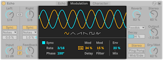
You can choose from one of six different modulation waveforms including sine, triangle, sawtooth up, sawtooth down, square, and noise. The selected waveform will appear in the display, which you can drag to adjust the modulation frequency.
When Sync is enabled, modulation is synchronized to the song tempo. You can use the Rate slider to set the frequency of the modulation oscillator in beat divisions. When Sync is disabled, you can use the Freq slider to adjust frequency of the modulation oscillator in Hertz.
Phase adjusts the amount of offset between the waveforms for the left and right channel. At 180°, the channels will be perfectly out of phase.
Mod Delay adjusts the amount of modulation that is applied to the delay time. Modulation x4 scales the delay time modulation depth by a factor of four. With short delay times, this produces deep flanging sounds.
Mod Filter adjusts the amount of modulation that is applied to the filter.
Env Mix blends between the modulation oscillator and an envelope follower. At 100%, only the envelope’s modulation will be heard. At 0%, only the LFO’s modulation will be heard.
28.14.3 Character Tab
Echo’s Character tab contains parameters that control dynamics and add imperfections to your sound.
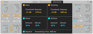
Gate enables a gate at Echo’s input. It mutes the signal components below its threshold. Threshold sets the threshold level that incoming audio signals must exceed in order to open the gate. Release sets how long it takes for the gate to close after the signal has dropped below the threshold.
When Ducking is enabled, the wet signal is proportionally reduced as long as there is an input signal. Ducking begins to affect the output signal when the input level exceeds the set Threshold. Release sets how long it takes for ducking to stop after the input signal drops below the threshold.
When enabled, Noise introduces noise to simulate the character of vintage equipment. You can adjust the Amount of noise added to the signal, and Morph between different types of noise.
When enabled, Wobble adds an irregular modulation of the delay time to simulate tape delays. You can adjust the Amount of wobble added to the signal, and Morph between different types of wobble modulation.
Repitch causes a pitch variation when changing the delay time, similar to the behavior of hardware delay units. When Repitch is disabled, changing the delay time creates a crossfade between the old and new delay times.
Note that in order to save CPU, the Echo device turns itself off at least eight seconds after its input stops producing sound. However, Echo will not switch off if both the Noise and Gate parameters are enabled.
28.14.4 Global Controls
The Reverb knob sets the amount of reverb added, and you use the Reverb Location chooser to set where the reverb is added in the processing chain: pre delay, post delay, or within the feedback loop. Use the Decay slider to lengthen or shorten the reverb tail.
The Stereo control sets the stereo width of the wet signal. 0% yields a mono signal whereas values above 100% create a widened stereo panorama.
The Output sets the amount of gain applied to the processed signal. The Dry/Wet control adjusts the balance between the processed and dry signals. Set it to 100 percent when using Echo in a return track. The Dry/Wet parameter’s context menu lets you toggle Equal-Loudness. When enabled, a 50/50 mix will sound equally loud for most signals.
28.15 EQ Eight
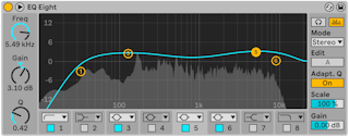
The EQ Eight effect is an equalizer featuring up to eight parametric filters per input channel, useful for changing a sound’s timbre.
The input signal can be processed using one of three modes: Stereo, L/R and M/S. Stereo mode uses a single curve to filter both channels of a stereo input equally. L/R mode provides an independently adjustable filter curve for the left and right channels of a stereo input; M/S mode (Mid/Side) provides the same functionality for signals that have been recorded using M/S encoding. In all modes, the frequency spectrum of the output is displayed behind the filter curves when the Analyze switch is on.
When using the L/R and M/S modes, both curves are displayed simultaneously for reference, although only the active channel is editable. The Edit switch indicates the active channel, and is used to toggle between the two curves.
Each filter has a chooser that allows you to switch between eight responses. From top to bottom in the choosers, these are:
- 48 or 12 dB/octave Low cut (cuts frequencies below the specified frequency);
- Low shelf (boosts or cuts frequencies lower than the specified frequency);
- Peak (boosts or cuts over a range of frequencies);
- Notch (sharply cuts frequencies within a narrow range);
- High shelf (boosts or cuts frequencies higher than the specified frequency);
- 12 or 48 dB/octave High cut (cuts frequencies above the specified frequency).
Each filter band can be turned on or off independently with an activator switch below the chooser. Turn off bands that are not in use to save CPU power. To achieve really drastic filtering effects, assign the same parameters to two or more filters.
To edit the filter curve, click and drag on the filter dots in the display. Drag-enclose multiple filter dots to adjust them simultaneously, either with the mouse or with your computer keyboard’s arrow keys. Horizontal movement changes the filter frequency, while vertical movement adjusts the filter band’s gain. To adjust the filter Q (also called resonance or bandwidth), hold down the Alt (Win) / Option (Mac) modifier while dragging the mouse. Note that the gain cannot be adjusted for the low cut, notch and high cut filters. In these modes, vertical dragging adjusts the filter Q.
To get an even better view, you can toggle the location of the display between the device chain and Live’s main window by clicking the  button in EQ Eight’s title bar. When using this expanded view, all eight filters can be edited simultaneously in the Device View.
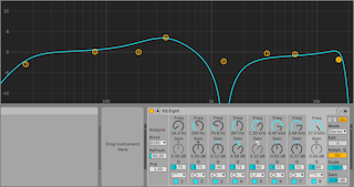
By default, EQ Eight’s output spectrum is shown in the display. If you would prefer to work entirely “by ear,” you can turn off the Analyze button to disable the spectrum view.
With Adaptive Q enabled, the Q amount increases as the amount of boost or cut increases. This results in a more consistent output volume and is based on the behavior of classic analog EQs.
To temporarily solo a single filter, enable Audition mode via the headphone icon. In Audition mode, clicking and holding on a filter dot allows you to hear only that filter’s effect on the output.
You can also select a band for editing by clicking near its number and then edit parameter values with the Freq, Gain and Q dials (and/or type values into the number fields below each dial).
As boosting will increase levels and cutting will decrease levels, use the global Gain slider to optimize the output level for maximum level consistent with minimum distortion.
The Scale field will adjust the gain of all filters that support gain (all except low cut, notch and high cut).
28.15.0.1 Context Menu Options for EQ Eight
Several of EQ Eight’s controls are only available via the device title bar’s context menu. These include:
- Oversampling - enabling this option causes EQ Eight to internally process two times the current sample rate, which allows for smoother filter behavior when adjusting high frequencies. There is a slight increase in CPU usage with Oversampling enabled.
28.16 EQ Three
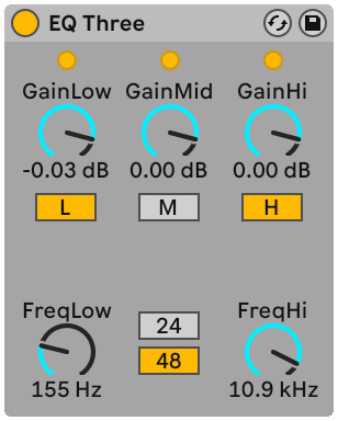
If you have ever used a good DJ mixer you will know what this is: An EQ that allows you to adjust the level of low, mid and high frequencies independently.
Each band can be adjusted from -infinite dB to +6 dB using the gain controls. This means that you can completely remove, for example, the bass drum or bassline of a track, while leaving the other frequencies untouched.
You can also turn on or off each band using the On/Off buttons located under the gain controls. These buttons are especially handy if assigned to computer keys.
EQ Three gives you visual confirmation of the presence of a signal in each frequency band using three LEDs. Even if a band is turned off, you can tell if there is something going on in it. The internal threshold for the LEDs is set to -24 dB.
The frequency range of each band is defined via two crossover controls: FreqLo and FreqHi. If FreqLo is set to 500 Hz and FreqHi to 2000 Hz, then the low band goes from 0 Hz to 500 Hz, the mid band from 500 Hz to 2000 Hz and the high band from 2000 Hz up to whatever your soundcard or sample rate supports.
A very important control is the 24 dB/48 dB switch. It defines how sharp the filters are cutting the signal at the crossover frequency. The higher setting results in more drastic filtering, but needs more CPU.
Note: The filters in this device are optimized to sound more like a good, powerful analog filter cascade than a clean digital filter. The 48 dB Mode especially does not provide a perfect linear transfer quality, resulting in a slight coloration of the input signal even if all controls are set to 0.00 dB. This is typical behavior for this kind of filter, and is part of EQ Three’s unique sound. If you need a more linear behavior choose 24 dB Mode or use the EQ Eight.
28.17 Erosion
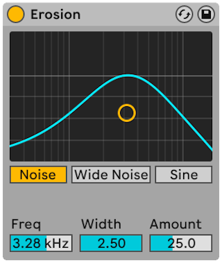
The Erosion effect degrades the input signal by modulating a short delay with filtered noise or a sine wave. This adds noisy artifacts or aliasing/downsampling-like distortions that sound very ”digital.”
To change the sine wave frequency or noise band center frequency, click and drag along the X-axis in the X-Y field. The Y-axis controls the modulation amount. If you hold down the Alt (Win) / Option (Mac) modifier key while clicking in the X-Y field, the Y-axis controls the bandwidth. Note that bandwidth is not adjustable when Sine is selected.
The Frequency control determines the color, or quality, of the distortion. If the Mode control is set to Noise, this works in conjunction with the Width control, which defines the noise bandwidth. Lower values lead to more selective distortion frequencies, while higher values affect the entire input signal. Width has no effect in Sine Mode.
Noise and Sine use a single modulation generator. However, Wide Noise has independent noise generators for the left and right channels, which creates a subtle stereo enhancement.
28.18 External Audio Effect
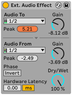
The External Audio Effect is a bit different than Live’s other effects devices. Instead of processing audio itself, it allows you to use external (hardware) effects processors within a track’s device chain.
The Audio To chooser selects the outputs on your computer’s audio hardware that will go to your external device, while the Audio From chooser selects the inputs that will bring the processed signal back into Live. As with the track inputs and outputs, the list of available inputs and outputs depends on the Audio Settings, which can be reached via the ”Configure…” option at the bottom of each chooser.
Below each chooser is a Peak level indicator that shows the highest audio level attained. Click on the indicators to reset them.
The Gain knobs next to the choosers adjust the levels going out of and back into Live. These levels should be set carefully to avoid clipping, both in your external hardware and when returning the audio to your computer.
The Dry/Wet control adjusts the balance between the processed and dry signals. Set it to 100 percent if using the External Audio Effect in a return track.
The Invert button inverts the phase of the processed signal coming back into Live.
Since hardware effects introduce latency that Live cannot automatically detect, you can manually compensate for any delays by adjusting the Hardware Latency slider. The button next to this slider allows you to set your latency compensation amount in either milliseconds or samples. If your external device connects to Live via a digital connection, you will want to adjust your latency settings in samples, which ensures that the number of samples you specify will be retained even when changing the sample rate. If your external device connects to Live via an analog connection, you will want to adjust your latency settings in milliseconds, which ensures that the amount of time you specify will be retained when changing the sample rate. Note that adjusting in samples gives you finer control, so even in cases when you’re working with analog devices, you may want to ”fine tune” your latency in samples in order to achieve the lowest possible latency. In this case, be sure to switch back to milliseconds before changing your sample rate.
Note: If the Delay Compensation option is unchecked in the Options menu, the Hardware Latency slider is disabled.
For instructions on how to accurately set up latency compensation for your hardware, please see the Driver Error Compensation lesson in Live’s Help View.
28.19 Filter Delay
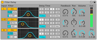
The Filter Delay provides three independent delay lines, each preceded by linked low-pass and high-pass filters. This allows applying delay to only certain input signal frequencies, as determined by the filter settings. The feedback from each of the three delays is also routed back through the filters.
Each of the three delays can be switched on and off independently. The Filter Delay device assigns delay 1 to the input signal’s left channel, delay 2 to the left and right channels and delay 3 to the right channel. The Pan controls at the right can override the delay channels’ outputs; otherwise each delay outputs on the channel from which it derives its input.
Each delay channel’s filter has an associated On switch, located to the left of each X-Y controller. The X-Y controllers adjust the low-pass and high-pass filters simultaneously for each delay. To edit filter bandwidth, click and drag on the vertical axis; click and drag on the horizontal axis to set the filter band’s frequency.
To refer delay time to the song tempo, activate the Sync switch, which allows using the Delay Time beat division chooser. The numbered switches represent time delay in 16th notes. For example, selecting ”4” delays the signal by four 16th notes, which equals one beat (a quarter note) of delay. With Sync Mode active, changing the Delay Time field percentage value shortens and extends delay times by fractional amounts, thus producing the ”swing” type of timing effect found in drum machines.
If the Sync switch is off, the delay time reverts to milliseconds. In this case, to edit the delay time, click and drag up or down in the Delay Time field, or click in the field and type in a value.
The Feedback parameter sets how much of the output signal returns to the delay line input. Very high values can lead to runaway feedback and produce a loud oscillation — watch your ears and speakers if you decide to check out extreme feedback settings!
Each delay channel has its own volume control, which can be turned up to +6 dB to compensate for drastic filtering at the input.
The Dry control adjusts the unprocessed signal level. Set it to minimum if using Delay in a return track.
28.20 Gate
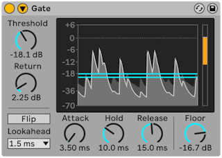
The Gate effect passes only signals whose level exceeds a user-specified threshold. A gate can eliminate low-level noise that occurs between sounds (e.g., hiss or hum), or shape a sound by turning up the threshold so that it cuts off reverb or delay tails or truncates an instrument’s natural decay.
Gate’s display area shows the level of the input signal in light gray and the level of the output signal in a darker gray with a white outline. This allows you to see the amount of gating that is occurring at any moment, and helps you to set the appropriate parameters.
The Threshold knob sets the gate’s sensitivity. The Threshold value is represented in the display as a horizontal blue line, which can also be dragged.
Return (also known as “hysteresis”) sets the difference between the level that opens the gate and the level that closes it. Higher hysteresis values reduce “chatter” caused by the gate rapidly opening and closing when the input signal is near the threshold level. The Return value is represented in the display as an additional horizontal orange line.
With the Flip button enabled, the gate works in reverse; the signal will only pass if its level is below the threshold.
A gate can only react to an input signal once it occurs. Since it also needs to apply an attack/release envelope, the gating is always a bit too late. A digital gate can solve this problem by simply delaying the input signal a little bit. Gate offers three different Lookahead times: zero ms, one ms and ten ms. The results may sound pretty different depending on this setting.
The Attack time determines how long it takes for the gate to switch from closed to open when a signal goes from below to above the threshold. Very short attack times can produce sharp clicking sounds, while long times soften the sound’s attack.
When the signal goes from above to below the threshold, the Hold time kicks in. After the hold time expires, the gate closes over a period of time set by the Release parameter.
The Floor knob sets the amount of attenuation that will be applied when the gate is closed. If set to -inf dB, a closed gate will mute the input signal. A setting of 0.00 dB means that even if the gate is closed, there is no effect on the signal. Settings in between these two extremes attenuate the input to a greater or lesser degree when the gate is closed.
Normally, the signal being gated and the input source that triggers the gate are the same signal. But by using sidechaining, it is possible to gate a signal based on the level of another signal. To access the Sidechain parameters, unfold the Gate window by toggling the button in its title bar.
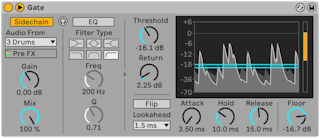
Enabling this section with the Sidechain button allows you to select another track from the choosers below. This causes the selected track’s signal to act as the gate’s trigger, instead of the signal that is actually being gated.
The Gain knob adjusts the level of the external sidechain’s input, while the Dry/Wet knob allows you to use a combination of sidechain and original signal as the gate’s trigger. With Dry/Wet at 100%, the gate is triggered entirely by the sidechain source. At 0%, the sidechain is effectively bypassed. Note that increasing the gain does not increase the volume of the source signal in the mix. The sidechain audio is only a trigger for the gate and is never actually heard.
Sidechain gating can be used to superimpose rhythmic patterns from one source onto another. For example, a held pad sound can be triggered with the rhythm of a drum loop by inserting a Gate on the pad’s track and choosing the drum loop’s track as the sidechain input.
On the right of the external section are the controls for the sidechain EQ. Enabling this section causes the gate to be triggered by a specific band of frequencies, instead of a complete signal. These can either be frequencies in the signal to be gated or, by using the EQ in conjunction with an external sidechain, frequencies in another track’s audio.
The headphones button between the external and EQ sections allows you to listen to only the sidechain input, bypassing the gate’s output. Since the sidechain audio isn’t fed to the output, and is only a trigger for the gate, this temporary listening option can make it much easier to set sidechain parameters and hear what’s actually making the gate work. When this button is on, the display area shows the level of the sidechain input signal in green.
28.21 Glue Compressor
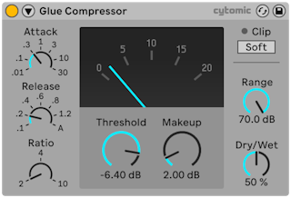
The Glue Compressor is an analog-modeled compressor created in collaboration with Cytomic, and is based on the classic bus compressor from a famous 80’s mixing console. Like Live’s original Compressor, the Glue Compressor can be used for basic dynamics control of individual tracks, but is mainly designed for use on the Main track or a Group Track to “glue” multiple sources together into a cohesive sounding mix.
The Threshold knob sets where compression begins. Signals above the threshold are attenuated by an amount specified by the Ratio parameter, which sets the ratio between the input and output signal. Unlike the Compressor, the Glue Compressor does not have a user-adjustable knee. Instead, the knee becomes more sharp as the ratio increases.
Attack defines how long it takes to reach maximum compression once a signal exceeds the threshold. The Attack knob’s values are in milliseconds. Release sets how long it takes for the compressor to return to normal operation after the signal falls below the threshold. The Release knob’s values are in seconds. When Release is set to A (Auto), the release time will adjust automatically based on the incoming audio. The Glue Compressor’s Auto Release actually uses two times - a slow one as a base compression value, and a fast one to react to transients in the signal. Auto Release may be too slow to react to sudden changes in level, but generally is a useful way to tame a wide range of material in a gentle way.
Dry/Wet adjusts the balance between the compressed and uncompressed signals. At 100%, only the compressed signal is heard, while at 0%, the device is effectively bypassed. Another way of controlling the amount of compression is with the Range slider, which sets how much compression can occur. Values between about -60 and -70 dB emulate the original hardware, while values between -40 and -15 dB can be useful as an alternative to the Dry/Wet control. At 0 dB, no compression occurs.
Makeup applies gain to the signal, allowing you to compensate for the reduction in level caused by compression. A Makeup value that roughly corresponds to the position of the needle in the display should result in a level close to what you had before compressing.
The Soft clip switch toggles a fixed waveshaper, useful for taming very loud transients. When enabled, the Glue Compressor’s maximum output level is -.5 dB. Note that with Oversampling enabled, very loud peaks may still exceed 0 dB. The Soft clipper is not a transparent limiter, and will distort your signal when active. We recommend leaving it disabled unless this particular type of “colored” distortion is what you’re looking for.
The Glue Compressor’s needle display shows the amount of gain reduction in dB. The Clip LED turns red if the device’s output level is exceeding 0 dB. If Soft clipping is enabled, this LED turns yellow to indicate that peaks are being clipped.
28.21.1 Sidechain Parameters
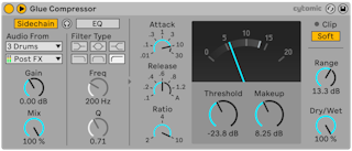
Normally, the signal being compressed and the input source that triggers the compressor are the same signal. But by using sidechaining, it is possible to compress a signal based on the level of another signal or a specific frequency component. To access the Sidechain parameters, unfold the Glue Compressor window by toggling the button in its title bar.
The sidechain parameters are divided into two sections. On the left are the external controls. Enabling this section with the Sidechain button allows you to select any of Live’s internal routing points from the choosers below. This causes the selected source to act as the Glue Compressor’s trigger, instead of the signal that is actually being compressed.
The Gain knob adjusts the level of the external sidechain’s input, while the Dry/Wet knob allows you to use a combination of sidechain and original signal as the Glue Compressor’s trigger. With Dry/Wet at 100%, the Glue Compressor is triggered entirely by the sidechain source. At 0%, the sidechain is effectively bypassed. Note that increasing the gain does not increase the volume of the source signal in the mix. The sidechain audio is only a trigger for the Glue Compressor and is never actually heard.
On the right of the external section are the controls for the sidechain EQ. Enabling this section causes the Glue Compressor to be triggered by a specific band of frequencies, instead of a complete signal. These can either be frequencies in the compressed signal or, by using the EQ in conjunction with an external sidechain, frequencies in another track’s audio.
The headphones button between the external and EQ sections allows you to listen to only the sidechain input, bypassing the Glue Compressor’s output. Since the sidechain audio isn’t fed to the output, and is only a trigger for the Glue Compressor, this temporary listening option can make it much easier to set sidechain parameters and hear what’s actually making the Glue Compressor work.
28.21.1.1 Context Menu Options for Glue Compressor
Oversampling can be toggled on or off via the device title bar’s context menu. Enabling this option causes the Glue Compressor to internally process at two times the current sampling rate, which may reduce aliasing and transient harshness. There is a slight increase in CPU usage with Oversampling enabled. Note that with Oversampling enabled, the level may exceed 0 dB even with Soft clip enabled.
28.22 Grain Delay
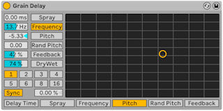
The Grain Delay effect slices the input signal into tiny particles (called ”grains”) that are then individually delayed and can also have different pitches compared to the original signal source. Randomizing pitch and delay time can create complex masses of sound and rhythm that seem to bear little relationship to the source. This can be very useful in creating new sounds and textures, as well as getting rid of unwelcome house guests, or terrifying small pets (just kidding!).
You can route each parameter to the X-Y controller’s horizontal or vertical axis. To assign a parameter to the X-axis, choose it from the parameter row below the controller. To assign a parameter to the Y-axis, use the parameter row on the left side.
To refer delay time to the song tempo, activate the Sync switch, which allows using the Delay Time beat division chooser. The numbered switches represent time delay in 16th notes. For example, selecting ”4” delays the signal by four 16th notes, which equals one beat (a quarter note) of delay. With Sync Mode active, changing the Delay Time field percentage value shortens and extends delay times by fractional amounts, thus producing the ”swing” type of timing effect found in drum machines.
If the Sync switch is off, the delay time reverts to milliseconds. In this case, to edit the delay time, click and drag up or down in the Delay Time field, or click in the field and type in a value.
The Delay Time can also be routed to the horizontal axis of the X-Y controller.
The Spray control adds random delay time changes. Low values smear the signal across time, which adds ”noisiness” to the sound. High Spray values completely break down the structure of the source signal, introducing varying degrees of rhythmic chaos. This is the recommended setting for anarchists.
The size and duration of each grain is a function of the Frequency parameter. The sound of Pitch and Spray depends very much on this parameter.
You can transpose the grain pitch with the Pitch parameter, which acts much like a crude pitch shifter.
The Random Pitch control adds random variations to each grain’s pitch. Low values create a sort of mutant chorusing effect, while high values can make the original source pitch completely unintelligible. This parameter can interact with the main Pitch control, thus allowing degrees of stability and instability in a sound’s pitch structure.
The Feedback parameter sets how much of the output signal returns to the delay line input. Very high values can lead to runaway feedback and produce a loud oscillation — watch your ears and speakers if you decide to check out extreme feedback settings!
Grain Delay also has a dry/wet control, which can be routed to the vertical axis of the X-Y controller.
28.23 Hybrid Reverb
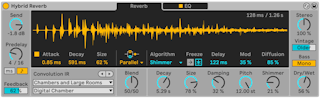
Hybrid Reverb combines two different approaches to reverberation in one device, blending convolution reverb with a number of digital reverb algorithms. Using multiple routing options and parameters, you can create unique reverb sounds, or use Hybrid Reverb to generate drone-like soundscapes or completely transform any source material.
In addition to providing a selection of impulse responses, Hybrid Reverb allows you to import any audio file to use as an impulse response (also known as an IR), greatly increasing your sound design opportunities. Dedicated controls can be employed to shape any chosen impulse response.
The algorithmic engine contains several reverb modes, each providing a different set of parameters and sonic properties, ranging from clean and creamy to metallic and gong-like.
The convolution and algorithmic engines can be used independently, or combined together in series or parallel, with their volume relationship being continuously adjustable. An EQ section further shapes the reverb’s sound and can be selectively applied to the two reverb engines. An additional control introduces degradation of the signal, emulating the behavior of older digital reverb units.
28.23.1 Signal Flow
You can imagine signals being processed by Hybrid Reverb as flowing from the left side of the device towards the right side, passing first through the input section, then into the reverb engines. The relationship between the two reverb engines is affected by the routing section, after which the signal passes through the EQ section, and then finally to the output.
The convolution reverb engine’s controls are yellow in color, while the algorithmic engine’s controls are displayed in blue.
28.23.2 Input Section
Using the Send knob, you can choose the amount of gain applied to the signal that feeds the reverb. Note that the dry signal is not affected and will still pass through the device.
Predelay controls the delay time before the onset of the first early reflection. This delays the reverberation relative to the input signal. One’s impression of the size of a real room depends partly on this delay; typical values for “natural” sounds range from 1ms to 25ms. You can choose either a time-based or beat-synced predelay time using the Predelay Sync buttons.
Feedback sets the amount of the predelay’s output that is fed back to its input. Note that both time-based and beat-based predelay times have independent feedback settings.
The main window of Hybrid Reverb has two tabs: Reverb and EQ. The Reverb tab contains all controls related to both the convolution and algorithmic reverb engines. Starting with the Routing chooser in the center, you’ll find four options:
- Serial routes the output of the convolution engine into the algorithmic engine. While the convolution reverb is always active in this mode, Blend controls the amount of convolution reverb fed into the algorithmic reverb. A setting of 100/0 produces pure convolution reverb, while 0/100 generates pure algorithmic reverb which has been fed by the convolution reverb’s output.
- Parallel uses both convolution and algorithmic reverb engines, but separates them from each other. The Blend knob adjusts the level balance between the two different reverb engines, with a setting of 100/0 generating pure convolution reverb and 0/100 producing pure algorithmic reverb.
- Algorithm uses only the algorithmic reverb engine.
- Convolution uses only the convolution reverb engine.
Hybrid Reverb’s user interface changes dynamically, so that when a reverb engine is not in use, its controls will appear grayed out.
The Blend knob blends between the output of the convolution and algorithm sections when Routing is set to Serial or Parallel. Note that when either Algorithm or Convolution is selected in the Routing chooser, the Blend knob will not have an effect.
28.23.3 Convolution Reverb Engine
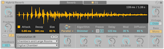
A convolution reverb uses recordings of actual spaces (called impulse responses) to create its effect. This allows you to place your sounds in practically any space for which you have a recording. For a more typical reverb sound, this can include some of the most famous halls and studios throughout the world. With a more creative approach, you can use recordings of anything, from snare drums to garbage cans, or even instrumental and vocal recordings!
Impulse responses can be chosen in the Convolution IR menu. The upper drop-down menu chooses the category of impulse response, while the lower drop-down menu chooses a specific impulse response from within that category. Backward and forward arrow buttons are provided for easy browsing through impulse responses. These arrow buttons will automatically switch to the next category when you reach the end of the current one, so you can continuously move through the impulse responses using the arrows alone. The chosen impulse response’s waveform is then shown in the main display, which changes based on the Attack, Decay, and Size settings (described below).
The various impulse response categories are: Early Reflections, Real Places, Chambers and Large Rooms, Made for Drums, Halls, Plates, Springs, Bigger Spaces, Textures, and User.
To add your own impulse responses to the User category, drag and drop the IR audio file into Hybrid Reverb’s convolution waveform display. If you add a file from a folder that contains other audio files, all files will be added as impulse responses. Note: if you remove Hybrid Reverb from a track and add it again, the previously added User samples will no longer be available in the User category. However, you can drag and drop the samples into the waveform display again to repopulate the list.
The Attack, Decay, and Size parameters control the impulse response’s amplitude envelope. The Attack parameter controls the attack time of the envelope, while the Decay parameter controls the decay time of the envelope. The Size parameter adjusts the relative size of the impulse response.
28.23.4 Algorithmic Reverb Engine
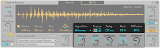
In comparison to the convolution engine, the algorithmic engine is based purely on digital delay lines, and no samples are used.
To the right of the Blend knob you will find the controls for the algorithmic reverb engine. Different parameters will be displayed depending on what you choose in the Algorithm chooser.
Five different algorithms are available: Dark Hall, Quartz, Shimmer, Tides and Prism. For all algorithms, the Decay, Size, Delay and Freeze parameters are available.
Decay adjusts the approximate time required for the algorithm’s reverb tail to drop to 1/1000th (-60 dB) of its initial amplitude. Size controls the size of the virtual room. Delay sets an additional predelay time in milliseconds for the algorithm section.
The Freeze controls consist of two buttons, Freeze and Freeze In. Freeze disables any input to the reverb engine and sets the algorithm’s decay time to infinite, so that reverb output will sustain endlessly. When enabled, Freeze In adds the input signal to the frozen reverberation, leading to a build-up of reverberated sound.
Each algorithm and their unique parameters are described in further detail below.
28.23.4.1 Dark Hall
The Dark Hall algorithm is a smooth and classic sounding algorithm suitable for most medium to long sounding halls.
In addition to the shared parameters listed above, Dark Hall also provides the following:
- Damping controls the amount of high-frequency filtering within the reverb algorithms. Higher values result in darker reverberation sounds.
- Mod controls the amount of movement within the algorithm’s reverb tail. Less modulation produces less movement, and more modulation creates more movement with a chorusing effect, while diminishing the effect of resonances.
- Shape transforms the artificial space’s sonic characteristics from small and resonant to large and diffused.
- Bass X controls the crossover frequency of the low-end part of the reverb tail, which is scaled using the Bass Mult control.
- Bass Mult scales the decay time of the low-end of the reverb tail.
In Dark Hall mode, long decay times combined with extremely small Size values create metallic gong-like resonances.
28.23.4.2 Quartz
The Quartz algorithm is a hall-like reverb with some audible echoes in the reverb’s tail. This reverb has a very clear replication of the input in the early reflections and is well suited for voices, drums and signals with clear transients, as well as making echoes.
In addition to the shared parameters listed above, Quartz also provides the following:
- Damping controls the amount of high-frequency filtering within the reverb algorithms. Higher values result in darker reverberation sounds.
- Lo Damp controls the amount of low frequency filtering within the reverb algorithms. Higher values result in brighter reverberation sounds.
- Mod controls the amount of movement within the algorithm’s reverb tail. Less modulation produces less movement, and more modulation creates more movement with a chorusing effect, while diminishing the effect of resonances.
- Diffusion controls the density of the algorithm’s reverb tail. Low values produce sparser tails, while higher values produce denser tails.
- Distance controls the virtual distance of reflections. Lower values put them closer to the listener and increase their density while higher values place them farther away and increase the time between echoes.
28.23.4.3 Shimmer
The Shimmer reverb algorithm is made from densely stacked diffuse delays with a pitch shifter in the feedback. Low diffusion values result in a pure delay, while high diffusion values result in a dense and lush artificial reverb. The Shimmer effect crossfades the pitch-shifted signal into the feedback, resulting in tails that climb or descend in frequency.
In addition to the shared parameters listed above, Shimmer also provides the following:
- Damping controls the amount of high-frequency filtering within the reverb algorithms. Higher values result in darker reverberation sounds.
- Mod controls the amount of movement within the algorithm’s reverb tail. Less modulation produces less movement, and more modulation creates more movement with a chorusing effect, while diminishing the effect of resonances.
- Pitch adjusts the degree of pitch-shifting applied to the feedback signal in semitones.
- Diffusion controls the density of the algorithm’s reverb tail. Low values produce sparser tails, while higher values produce denser tails. Turn this below 10% for dub-like delay effects. This is very fun to use on drums!
- Shimmer adjusts the intensity of the Shimmer effect. When set to 0%, no pitch shifting is applied; the level of the pitched signal is progressively more present as the percentage is increased. When used on melodic material, setting Shimmer to 100% produces interesting pitch harmonizations.
In Shimmer mode, the Size knob adjusts the distance between individual echoes on percussive material.
28.23.4.4 Tides
The Tides algorithm uses a smooth reverb while modulating the output’s spectrum with a multiband filter, creating rippling frequency band effects.
In addition to the shared parameters listed above, Tides also provides the following:
- Damping controls the amount of high-frequency filtering within the reverb algorithms. Higher values result in darker reverberation sounds.
- Wave morphs the filter modulation waveform from noise (0%) to sine (50%) to square (100%).
- Tide adjusts the intensity of texture created by the modulation of the reverb tail.
- Phase adjusts the amount of offset between the modulation waveforms for the left and right channel. At 180°, the channels will be perfectly out of phase.
- Rate sets the rate of the modulation oscillator in beat divisions with Triplet, 16th, and Dotted note value variations.
28.23.4.5 Prism
The Prism algorithm is a bright, unique and artificial-sounding diffuse reverb based on velvet (spectrally flat) noise. This algorithm can easily be used as a “ghost” reverb, adding depth without interfering with the source material. It is well suited for non-linear short decays on drums and transient material but can be also used on more sustained sounds with longer decays to achieve a clean yet digital sound.
In addition to the shared parameters listed above, Prism also provides the following:
- Low Mult scales the decay time of the low-end of the reverb tail.
- High Mult scales the decay time of the high-end of the reverb tail.
- X over controls the crossover frequency between the low-frequency and high-frequency portions of the reverb tail, which in turn adjusts the frequency content affected by the Low Mult and High Mult parameters.
Tip: For a classic ‘80s-style gated snare reverb, use smaller Decay and Size values.
28.23.5 EQ Section
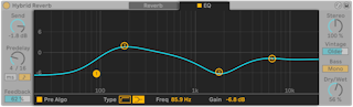
The EQ section of Hybrid Reverb is found in the second tab of the device’s display. You can quickly activate or deactivate it by clicking on its toggle button in the tab.
By default, the EQ is placed after both reverb engines in the signal chain; however, by toggling the Pre Algo button, you can place the EQ before the algorithmic reverb, regardless of which reverb routing you have chosen.
Four bands of control are provided to further shape the reverb signal. The low and high bands can be toggled between pass filters and shelving EQs. While in low-pass or high-pass mode, the filters provide a range of slopes, from a gentle 6 dB/octave to a steep 96 dB/octave. The two middle peak EQs can cover the entire frequency range and can be used for anything from wide-band boosting to semi-narrow cuts.
28.23.6 Output Section
Hybrid Reverb’s output section contains a final set of parameters to shape the device’s overall sound.
Stereo sets the stereo width of the wet signal. 0% yields a mono signal whereas values above 100% create a widened stereo panorama.
The Vintage slider increasingly degrades Hybrid Reverb’s sounds by emulating lower sample rates and bit-depths, as is common in vintage digital reverberation devices. Four presets can be used to radically alter the overall sound: Subtle, Old, Older, and Extreme.
Bass Mono converts frequencies lower than 180 Hz of Hybrid Reverb’s output signal to mono, which helps to make bass frequencies sound tighter.
The Dry/Wet control adjusts the balance between the processed and dry signals. Set it to 100% when using Hybrid Reverb in a return track.
28.24 Limiter
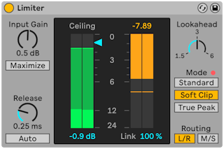
The Limiter effect is a mastering-quality dynamic range processor that ensures that the output does not exceed a specified level. Limiter is ideal for use on the Main track, to prevent clipping in digital-to-analog converters. A limiter is essentially a compressor with an infinite ratio. For more information about compression theory, refer to the Compressor section.
Limiter’s display contains the Ceiling control and the Gain Reduction meter. The Ceiling control sets the absolute maximum level that Limiter will output. If your incoming signal level has no peaks that are higher than the ceiling, no limiting will be applied by the device.
The Gain Reduction meter shows the amount of gain reduction being applied when the signal reaches the ceiling or threshold.
The Link control defines how much of the gain reduction applied by Limiter is shared across its two channels. These can be the left/right channels or the mid/side channels, depending on which Routing Mode is selected. When set to 100%, limiting is applied to both channels whenever either requires compression, ensuring a stable stereo image. When set to 0%, the channels are processed independently, with different gain reduction applied to each channel. This can be useful when working with signals where the left and right channels are separate, or to achieve creative effects, such as a “wobble” in the stereo image.
You can use the Input Gain knob to the left of the display to boost or attenuate the incoming signal level before limiting is applied to it.
Switching on the Maximize toggle below the Input Gain knob changes the Ceiling control to Threshold, which allows you to adjust the signal’s dynamic range and loudness with a single control. Lowering the Threshold amplifies the limiter stage output by the inverse of the Threshold value. Note that the Input Gain knob becomes the Output control when Maximize is on, and sets the target output level for the device.
The Release knob adjusts how long it takes for the device to stop applying limiting after the signal falls below the ceiling or threshold. Fast release times make the output sound louder and punchier, while slow release times add smoothness, though can also reduce the dynamic range. The Gain Reduction meter helps to visualize the effect of the Release control: at faster release times you will see the meter return to zero more quickly, while at slower release times the meter recovers more gradually, and Limiter maintains compression for a longer time.
You can use the Auto toggle beneath the Release knob to activate auto-release. When on, Limiter analyzes incoming audio and continuously updates its release time based on the signal’s characteristics. Note that when auto-release is enabled, the Release control is deactivated.
The Lookahead control to the right of the display allows you to adjust the setting that determines how quickly Limiter will respond to peaks that require compression. The lookahead time can be set to 1.5, 3, or 6 milliseconds. Shorter lookahead times allow for more compression but can increase distortion, especially when applied to bass sounds. As the lookahead time affects Limiter’s attack time, longer lookahead values are useful for catching very fast peaks. Note that lookahead introduces latency: the longer the lookahead time, the higher the latency.
The Ceiling Mode toggles let you choose between three ceiling modes: Standard, Soft Clip, and True Peak. Standard is the device’s default mode. Soft Clip introduces soft clipping when signals approach the device’s ceiling level, which can add subtle color and punch to transients. When Soft Clip is on, an LED appears above the mode toggles, and flashes to indicate that the signal is clipping. Finally, the True Peak mode prevents inter-sample peaks.
You can use the Routing Mode toggles to determine how Limiter treats peaks that occur on only one side of the stereo signal. In L/R mode, the left and right channels of the signal are compressed independently. This allows the device to apply more compression, but with some distortion of the stereo image. In M/S mode, Limiter encodes the signal to mid/side before the limiting stage, then decodes it to stereo at the output stage. This can be useful for preserving the signal’s stereo image, but results in higher latency.
Note that adding any further processing effects after Limiter may add gain. To ensure that your final output will never clip, place Limiter as the last device in the Main track’s device chain and keep the Main track’s volume below 0 dB.
28.25 Looper
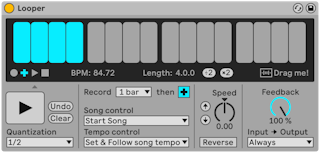
Looper is an audio effect based on classic real-time looping devices. It allows you to record and loop audio, creating endless overdubs that are synced to your Set. If the Set is not playing, Looper can analyze incoming audio and set Live’s tempo to match it. You can also predefine a loop length before recording and Live’s tempo will adjust so that your loop fits into the specified number of bars. Furthermore, audio can be imported to Looper to create a background for newly overdubbed material, or exported from Looper as a new clip.
The top half of Looper’s interface is a large display area optimized for easy readability during performance. During recording, the entire display area turns red. After recording, the display shows the current position in the loop and the total loop length in bars and beats.
Looper’s transport buttons work in a similar way to other transport controls in Live. The Record button records incoming audio until another button is pressed. This overwrites any audio currently stored in Looper. Overdub continues to add additional layers of incoming audio that are the length of the originally recorded material. The Play button plays back the current state of Looper’s buffer without recording any new material. The Stop button stops playback.
The behavior of the transport controls changes depending on whether or not Live’s playback is running. With the transport running, Looper behaves like a clip, and is subject to launch quantization as determined by the Quantization chooser. When Live’s playback is stopped, Looper’s transport engages immediately, regardless of the Quantization setting.
The Clear button erases Looper’s buffer. If you press Clear in Overdub mode while the transport is running, the contents of the buffer are cleared but the tempo and length are maintained. Pressing Clear in any other mode resets the tempo and length.
The Undo button erases everything that you’ve overdubbed since the last time Overdub was enabled. Your original recording, and anything that was overdubbed in a previous pass, is preserved. After pressing Undo, the button changes to Redo, which replaces the material removed by the last undo.
The large button below the transport controls is the Multi-Purpose Transport Button. As with the normal transport buttons, this button’s behavior changes depending on Looper’s current playback state, and whether or not material has already been recorded. If the buffer is empty, a single click starts recording. If Looper is recording, overdubbing or stopped, a single click switches to play mode. During playback, a click switches to overdub mode, allowing you to toggle back and forth between overdub and playback via additional single clicks.
Quickly pressing the button twice stops Looper, from either play or overdub mode. Clicking and holding the button for two seconds while in play mode activates Undo or Redo. Pressing and holding for two seconds while stopped clears Looper’s buffer.
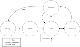
Looper’s Multi-Purpose Transport Button is optimized for use with a MIDI footswitch. To assign a footswitch, enter MIDI Map Mode, click the button and then press your attached footswitch. Then exit MIDI Map Mode.
The Tempo Control chooser affects how Looper determines the tempo of recorded material:
- None: Looper’s internal tempo is independent of Live’s global tempo.
- Follow song tempo: The speed of Looper’s playback will be adjusted so that the recorded material plays back at Live’s global tempo.
- Set & Follow song tempo: Live’s global tempo will be adjusted to match the tempo of material recorded into Looper. Any subsequent changes to Live’s global tempo will adjust the speed of Looper’s playback so that the recorded material plays back at the new global tempo.
The Record Length chooser is used to set the length of recorded material. Its behavior changes depending on whether or not Live’s global transport is running and, depending on the setting of the Tempo Control chooser, can set Live’s global tempo:
- Song running: If Looper’s Record Length chooser is set to the default ”x bars,” Looper will record until you press another transport button. If you specify a fixed number of bars to record by selecting another option in the chooser, Looper will record for the specified time and then switch to Play or Overdub, as determined by the button next to this chooser.
- Song not running: If Looper’s Record Length chooser is set to the default ”x bars,” Looper will make a guess about the tempo of the material you’ve recorded as soon as you press Overdub, Play or Stop. But this might result in a tempo that’s twice or half as fast as you’d like. If you first specify a fixed number of bars, Looper’s tempo will adjust so that your recording fits into this time.
The Song Control chooser determines how Looper’s transport controls will affect Live’s global transport:
- None means that Looper’s transport controls have no effect on Live’s global transport.
- Start Song will start Live’s global transport whenever Looper enters Play or Overdub mode. Looper’s Stop button has no effect on the global transport.
- Start & Stop Song locks Live’s global transport to Looper’s transport controls. Entering Play or Overdub mode will start Live’s transport, while pressing Looper’s Stop button will stop Live’s transport.
Starting playback of Live’s transport via Looper will automatically adjust the playback position of any apps that are connected via Ableton Link. This ensures that those apps remain tempo synced, and also at the correct position in the musical phrase.
The ”×2” button doubles the length of Looper’s recording buffer. Any material that you’ve already recorded will simply be duplicated. This allows you to, for example, record a series of one-bar ideas, and then overlay a series of two-bar ideas. The length and tempo of Looper’s buffer is shown in the display area.
Similarly, the ”÷2” button cuts the length of the current buffer in half. The material in the currently playing half is kept, while the other half is discarded.
The ”Drag me!” area in the display allows you to export Looper’s buffer as a new audio file. You can drag and drop to the browser or directly to a track, creating a new clip. The newly created clip’s Warp Mode will be set to Re-Pitch by default. You can also drag audio files to the ”Drag me!” area, which will replace the contents of Looper’s buffer. You can then use this material as a bed for further overdubs, for example.
The Speed knob adjusts Looper’s playback speed (and thus pitch). The up and down arrow buttons to the left are shortcuts to raise or lower the pitch by octaves (thus doubling or halving the playback speed). These buttons are subject to the Quantization chooser setting.
Enabling the Reverse button plays the previously recorded material backwards. Any material that you overdub after enabling Reverse will be played forward. Note that disabling Reverse will then swap this behavior; the original material will play forward again, while the material that was overdubbed while Reverse was enabled will play backwards. Engaging the Reverse button is subject to the Quantization chooser setting.
Feedback sets the amount of previously recorded signal that is fed back into Looper when overdubbing. When set to 100%, the previously recorded material will never decrease in volume. When set to 50%, it will be half as loud with each repetition. Any changes to the Feedback amount won’t take effect until the next repetition. Note that Feedback has no effect in Play mode; each repetition will be at the same volume.
The Input -> Output chooser provides four options for monitoring Looper’s input:
- Always allows the input signal to be heard regardless of Looper’s playing or recording state. You’ll typically want to choose Always when using Looper as an effect in a single track.
- Never means that the input signal will never be heard. You’ll typically want to choose Never when using Looper as an effect in a return track, where it may be fed by send levels from a variety of other tracks.
- Rec/OVR means that the input is only audible when recording or overdubbing, but not when Looper is in Play mode or stopped. This is useful for situations in which you are feeding audio to multiple tracks, each containing its own Looper. If each of these Loopers is controlled with its own foot pedal, you can switch the recording and playback state while playing an instrument, without having to worry about monitor settings.
- Rec/OVR/Stop allows the input signal to be heard except when Looper is in play mode. This is similar to Beat Repeat’s Insert mode, and can be used to record material that can suddenly interrupt your live playing.
28.25.1 Feedback Routing
Looper can be used as both a source and a target for internal routing to other tracks. This allows you to, for example, create Looper overdubs that continually feed back through another track’s devices. To set this up:
- Insert Looper on a track.
- Record at least one pass of material into Looper.
- Create another audio track.
- In the new track’s top Audio From and Audio To choosers, select the track containing the Looper.
- In the new track’s bottom Audio From and Audio To choosers, select ”Insert-Looper.”
- Switch this track’s Monitoring to ”In.”
- Add additional effects devices to the device chain of the new track.
- Put Looper into Overdub mode.
Looper’s output will now be routed through the other track’s device chain and then back into itself, creating increasingly processed overdub layers with each pass.
28.26 Multiband Dynamics
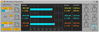
The Multiband Dynamics device is a flexible tool for modifying the dynamic range of audio material. Designed primarily as a mastering processor, Multiband Dynamics allows for upward and downward compression and expansion of up to three independent frequency bands, with adjustable crossover points and envelope controls for each band. Each frequency range has both an upper and lower threshold, allowing for two types of dynamics processing to be used simultaneously per band.
28.26.1 Dynamics Processing Theory
To understand how to use the Multiband Dynamics device, it helps to understand the four different methods of manipulating dynamics.
When we use the term “compression,” we’re typically talking about lowering the level of signals that exceed a threshold. This is how Live’s Compressor works, and is more accurately called downward compression because it pushes loud signals down, thus reducing the dynamic range. But it is also possible to reduce a signal’s dynamic range by raising the levels of signals that are below a threshold. This much-less-common form of compression is called upward compression. As you can see from this diagram, employing either type of compression results in a signal with a smaller dynamic range than the original.

The opposite of compression is expansion. A typical expander lowers the levels of signals that are below a threshold. This is how Live’s Gate works, and is more accurately called downward expansion because it pushes quiet signals down, thus increasing the dynamic range. It is also possible to increase a signal’s dynamic range by raising the levels of signals that are above a threshold. Like upward compression, this technique is known as upward expansion and is much less common. This diagram shows that either type of expansion results in a signal with a larger dynamic range.

To summarize:
- Downward compression (common): make loud signals quieter
- Upward compression (uncommon): make quiet signals louder
- Downward expansion (common): make quiet signals quieter
- Upward expansion (uncommon): make loud signals louder
The Multiband Dynamics device allows for all of these types of processing. In fact, because the device allows for incoming audio to be divided into three frequency bands, and each band has both an upper and lower threshold, a single instance of Multiband Dynamics can provide six types of dynamics processing simultaneously.
28.26.2 Interface and Controls
The High and Low buttons toggle the high and low bands on or off. With both bands off, the device functions as a single-band effect. In this case, only the Mid controls affect the incoming signal. The frequency sliders below the High and Low buttons adjust the crossovers that define the frequency ranges for each band. If the low frequency is set to 500 Hz and the high frequency is set to 2000 Hz, then the low band goes from 0 Hz to 500 Hz, the mid band from 500 Hz to 2000 Hz and the high band from 2000 Hz up to whatever your soundcard or sample rate supports.
Each band has activator and solo buttons. With the activator button disabled for a given band, its compression/expansion and gain controls are bypassed. Soloing a band mutes the others. The Input knobs boost or attenuate the level of each band before it undergoes dynamics processing, while the Output knobs to the right of the display adjust the levels of the bands after processing.
The display area provides a way of both visualizing your dynamics processing and adjusting the relevant compression and expansion behavior. For each band, the output level is represented by large bars, while the input level before processing is represented by small bars. With no processing applied, the input meters will be aligned with the top of the output meters. The scaling along the bottom of the display shows dB. As you adjust the gain or dynamics processing for a band, you can see how its output changes in comparison to its input.
As you move your mouse over the display, the cursor will change to a bracket as it passes over the edges of the blocks on the left or right side. These blocks represent the signal levels under the Below and over the Above thresholds, respectively. Dragging left or right on the edges of these blocks adjusts the threshold level. Holding down Ctrl (Win) / Cmd (Mac) while dragging a threshold will adjust the same threshold for all bands. Hold down Alt (Win) / Option (Mac) to simultaneously adjust the Above and Below thresholds for a single band. Holding down Shift while dragging left or right allows you to adjust the threshold of a single band at a finer resolution.
As you mouse over the middle of the block, the cursor will change to an up-down arrow. Click and drag up or down to make the signal within the selected volume range louder or quieter. Holding down Ctrl (Win) / Cmd (Mac) while dragging up or down will adjust the volume of the same block for all bands. Hold down Alt (Win) / Option (Mac) to simultaneously adjust the Above and Below volumes for a single band. Holding down Shift while dragging up or down allows you to adjust the volume of a single band at a finer resolution. Double-clicking within the region resets the volume to its default.
In technical terms, lowering the volume in the block above the Above threshold applies downward compression, while raising it applies upward expansion. Likewise, lowering the volume in the block below the Below threshold applies downward expansion, while raising it applies upward compression. In all cases, you are adjusting the ratio of the compressor or expander.
The thresholds and ratios of all bands can also be adjusted via the column to the right of the display. The ”T,” ”B” and ”A” buttons at the bottom right of the display area toggle between displaying the Time (attack and release), Below (threshold and ratio) and Above (threshold and ratio) for each band.
For the Above thresholds, Attack defines how long it takes to reach maximum compression or expansion once a signal exceeds the threshold, while Release sets how long it takes for the device to return to normal operation after the signal falls below the threshold.
For the Below thresholds, Attack defines how long it takes to reach maximum compression or expansion once a signal drops below the threshold, while Release sets how long it takes for the device to return to normal operation after the signal goes above the threshold.
With Soft Knee enabled, compression or expansion begins gradually as the threshold is approached.
The RMS/Peak switch also affects how quickly Multiband Dynamics responds to level changes. With Peak selected, the device reacts to short peaks within a signal. RMS mode causes it to be less sensitive to very short peaks and to begin processing only when the incoming level has crossed the threshold for a slightly longer time.
The global Output knob adjusts the overall output gain of the device.
The Time control scales the durations of all of the Attack and Release controls. This allows you to maintain the same relative envelope times, but make them all faster or slower by the same amount.
The Amount knob adjusts the intensity of the compression or expansion applied to all bands. At 0%, each compressor/expander has an effective ratio of 1, meaning that it has no effect on the signal.
28.26.3 Sidechain Parameters
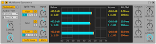
Normally, the signal being processed and the input source that triggers the device are the same signal. But by using sidechaining, it is possible to apply dynamics processing to a signal based on the level of another signal or a specific frequency component. To access the Sidechain parameters, unfold the Multiband Dynamics window by toggling the button in its title bar.
Enabling the Sidechain button allows you to select any of Live’s internal routing points from the choosers below. This causes the selected source to act as the device’s trigger, instead of the signal that is actually being processed.
The Gain knob adjusts the level of the external sidechain’s input, while the Dry/Wet knob allows you to use a combination of sidechain and original signal as the trigger. With Dry/Wet at 100%, the device is triggered entirely by the sidechain source. At 0%, the sidechain is effectively bypassed. Note that increasing the gain does not increase the volume of the source signal in the mix. The sidechain audio is only a trigger for the device and is never actually heard.
The headphones button allows you to listen to only the sidechain input, bypassing the device’s output. Since the sidechain audio isn’t fed to the output, and is only a trigger for the device, this temporary listening option can make it much easier to set sidechain parameters and hear what’s actually making the device work.
28.26.4 Multiband Dynamics Tips
Multiband Dynamics is a feature-rich and powerful device, capable of up to six independent types of simultaneous processing. Because of this, getting started can be a bit intimidating. Here are some real-world applications to give you some ideas.
28.26.4.1 Basic Multiband Compression
By using only the upper thresholds, Multiband Dynamics can be used as a traditional ”downward” compressor. Adjust the crossover points to suit your audio material, then apply downward compression (by dragging down in the upper blocks in the display or by setting the numerical ratios to values greater than 1.)
28.26.4.2 De-essing
To remove ”harshness” caused by overly loud high frequency content, try enabling only the upper band and setting its crossover frequency to around 5 kHz. Then gradually adjust the threshold and ratio to apply subtle downward compression. It may help to solo the band to more easily hear the results of your adjustments. Generally, de-essing works best with fairly fast attack and release times.
28.26.4.3 Uncompression
Mastering engineers are often asked to perform miracles, like adding punch and energy to a mix that has already been heavily compressed, and thus has almost no remaining transients. Most of the time, these mixes have also been heavily maximized, meaning that they also have no remaining headroom. Luckily, upward expansion can sometimes help add life back to such overly squashed material. To do this:
- Turn down the Input knob to provide some additional headroom.
- Adjust the Above thresholds for the bands so that they’re below the highest peaks.
- Add a small amount of upward expansion to each band. Be careful — excessive upward expansion can make transients very loud.
- Carefully adjust the attack and release times for each band. Note that, unlike in typical downward compression, very fast attack times will increase the impact of transients, while slower times result in a more muffled sound.
Note: Adding a maximizer or limiter to boost gain after you’ve returned some peaks to your material may simply destroy them again.
28.27 Overdrive
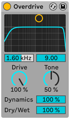
Overdrive is a distortion effect that pays homage to some classic pedal devices commonly used by guitarists. Unlike many distortion units, it can be driven extremely hard without sacrificing dynamic range.
The distortion stage is preceded by a band-pass filter that can be controlled with an X-Y controller. To define the filter bandwidth, click and drag on the vertical axis. To set the position of the frequency band, click and drag on the horizontal axis. These parameters can also be set via the slider boxes below the X-Y display.
The Drive control sets the amount of distortion. Note that 0% does not mean zero distortion!
Tone acts as a post-distortion EQ control. At higher values, the signal has more high-frequency content.
The Dynamics slider allows you to adjust how much compression is applied as the distortion is increased. At low settings, higher distortion amounts result in an increase in internal compression and make-up gain. At higher settings, less compression is applied.
The Dry/Wet control adjusts the balance between the processed and dry signals. Set it to 100 percent if using Overdrive in a return track.
28.28 Pedal
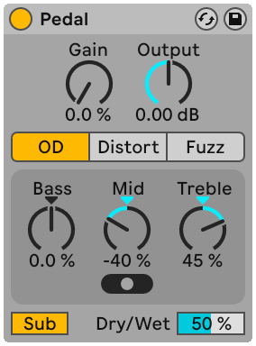
Pedal is a guitar distortion effect. In combination with Live’s Tuner, Amp and Cabinet effects, Pedal is great for processing guitar sounds. Pedal can also be used in less conventional settings, such as a standalone effect on vocals, synths or drums.
The Gain control adjusts the amount of distortion applied to the dry signal. Note that 0% does not mean zero distortion. It is recommended to dial the Gain back to 0% and slowly increase it until you get the desired output level. When placed in front of Pedal in a device chain, Utility’s Gain parameter can be used to lower the signal even further.
The global Output knob adjusts the overall output gain of the device.
You can choose between three different Pedal Types, each inspired by distortion pedals with their own distinct sonic characteristics:
- Overdrive: warm and smooth
- Distortion: tight and aggressive
- Fuzz: unstable, with a “broken amp” sound
Pedal has a three-band EQ that adjusts the timbre of the sound after the distortion is applied. The EQ is adaptive, which means that the amount of resonance (or “Q”) increases as the amount of EQ boost increases.
The Bass control is a peak EQ, with a center frequency of 100 Hz. This is useful for boosting the “punch” in bass or drum sounds, or attenuating low frequencies of guitars.
The Mid control is a three-way switchable boosting EQ. The Mid Frequency switch sets the center frequency and range of the Mid control. The center frequency is the middle of the frequency range that the Mid control operates upon. The frequency range around this center value is narrower in the lowest switch setting and wider in the higher setting. This is common in guitar pedals where it is normal to make tight cuts and boosts at low frequencies, and wider cuts and boosts at high frequencies.
The center frequencies for the switch settings are:
- Lowest setting, positioned on the left side: 500 Hz
- Middle setting, positioned in the center: 1 kHz
- Highest setting, positioned on the right side: 2 kHz
The Treble control is a shelving EQ, with a cutoff frequency of 3.3 kHz. This is useful for removing harsh high frequencies (or boosting them, if that’s your cup of tea!).
Tip: For a more fine-grained EQ post-distortion, simply leave these controls in their neutral position and instead use another EQ, such as EQ Eight.
The Sub switch toggles a low shelf filter that boosts frequencies below 250 Hz. You can use this in conjunction with the Bass control by turning Sub on and setting the Bass to -100%, or turning Sub off and setting the Bass to 100%.
The Dry/Wet slider adjusts the balance between the processed and dry signals.
Aliasing can be reduced by enabling Hi-Quality mode, which can be accessed via the device title bar’s context menu. This improves the sound quality, particularly with high frequency signals, but there is a slight increase in CPU usage.
28.28.1 Pedal Tips
28.28.1.1 Positioning Pedal in the Device Chain
The incoming signal will have an impact on how the distortion will respond. For example, adding a Compressor before Pedal in the device chain will give a more balanced end result. On the other hand, adding an EQ or filter with high gain and resonance settings before Pedal can yield a screaming distortion effect.
28.28.1.2 Techno Kick
Choose a suitable kick with a long decay (e.g., Kit-Core 909, with decay turned up). Then, choose the Distort pedal, activate the Sub switch, and dial in the Gain to your taste.
For added “whack”, move the Mid Frequency switch to the right-most position and increase the Mid control. For more “thump”, you can increase the Bass control.
To reduce the “air”, decrease the Treble control.
28.28.1.3 Drum Group Fizzle
To add “fizzle” to a drum group, choose the Fuzz pedal, increase the Gain to 50% and make sure the Sub switch is disabled.
Reduce the Bass and Mid controls to -100%, and adjust the Mid Frequency Switch to taste. Increase the Treble to 100%.
Set the Output to -20dB. Then, turn the Dry/Wet slider down to 0% and slowly increase it until the drums are fizzling to your taste.
28.28.1.4 Broken Speaker
Select the Fuzz pedal, and make sure the Sub switch is disabled. Turn down the Bass control completely, and set the Treble to 25%.
Set the Mid control 100% and move the Mid Frequency switch to right-most position. Finally, set the Gain control to 100%.
28.28.1.5 Sub Warmer
To add upper harmonics and warmth to a simple sub bass, choose the OD pedal, turn on the Sub switch and turn up the Bass control. Then, slowly increase the Gain until the desired effect is reached. You can then cut or boost the mid frequencies using the Mid control.
28.29 Phaser-Flanger
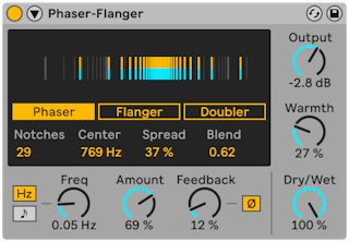
Phaser-Flanger combines the functionalities of flanger and phaser effects into one device with separate modes, and offers an additional Doubler mode. All modes can be used to create lush, expressive sounds with a wide variety of tools and detailed options. Two LFOs and an envelope follower provide plenty of modulation possibilities.
You can choose between the three modes in the display:
- Phaser, with its wide range of frequency and modulation ranges, creates wandering notch filters by feeding a phase-shifted version of the input signal back into the input. The phase shifting is achieved using modulated all-pass filters and has a lush sound.
- Flanger creates a continuously changing comb filter effect by adding a time-modulated delayed signal with feedback to the input.
- Doubler creates the effect of doubled tracks (multiple stacked versions of similar recording takes) by adding time-modulated delayed signals to the input.
The display contains a visualization and the mode selector buttons. The visualization presents different information depending on the mode you choose and the LFO Stereo Mode’s settings (described in more detail below).
In Phaser mode, the visualization shows the number of notches and their spectral positions.
Phaser’s parameters can be adjusted in the lower portion of the display.
Notches increases or decreases the number of all-pass filters being used. Center chooses the center frequency of the notches. Spread increases or decreases the distance between the notches by adjusting the Q factor of the all-pass filters. Blend mixes the modulation routing between Center Frequency and Spread, with Center Frequency at 0.0 and Spread at 1.0.
In Flanger mode, the visualization shows how the modulation signal is affecting the delay time, with the left-most position equaling the value chosen in the Time parameter. As the visualization moves to the right, the delay time decreases; as it moves to the left, it increases. Time adjusts the delay time of the Flanger delay lines.
In Doubler mode, the visualization acts differently than in Flanger mode. Modulation in Doubler mode is bipolar, meaning that, as the visualization moves to the right, the delay time increases; as it moves to the left, it decreases. Time adjusts the delay time of the Doubler delay lines.
For finer control over the sound, you can unfold the device by toggling the button in Phaser-Flanger’s title bar to reveal further options for the main LFO, as well as a second LFO, an envelope follower and a Safe Bass high-pass filter. Also shown is a visualization for the main LFO, in which its rate, waveform and the phase relationships of the stereo channels are shown.
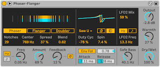
The main LFO’s speed is controlled by the Freq/Rate parameter, and can be either tempo-synced or free-running. Use the Modulation Sync buttons to the left of the dial to switch between Frequency and Sync Rate. When set to Hz, the corresponding Freq dial controls the LFO rate in Hertz; otherwise, the Rate dial will sync the LFO with the song tempo.
Multiple waveforms for the main LFO are available and can be found in the LFO Waveform chooser. These include Sine, Triangle (default), Saw Up, Saw Down, Rectangle, Random, and Random S&H (Sample and Hold). Also included are Triangle Analog, Triangle 8, Triangle 16, which are described below:
- Triangle Analog is a low-pass filtered rectangular waveform which changes shape and amplitude drastically for different LFO rates.
- Triangle 8 divides a period of a normal triangular wave into eight discrete steps.
- Triangle 16 divides a period of a normal triangular wave into 16 discrete steps.
The LFO Stereo Mode button switches between Phase and Spin modes, both of which allow modulation of each stereo channel independently.
When Phase is chosen, adjusting the Phase value will change the phase relationship between the left and right channels. At 180°, the phase of the left and right channels are completely inverted. This can be seen in the LFOs visualization.
When Spin is chosen, adjusting the Spin value detunes the two LFO rates relative to each other. This can be seen in the main display’s visualization.
Duty Cycle will change the time scale of the waveform’s period, compressing it towards either the front of the cycle (100%) or the back of the cycle (-100%). At 0%, the time scale of the period is spread equally across the entire cycle, leaving the waveform unaffected. This is similar to how Pulse Width affects rectangular waveforms, and its effects can be seen in the waveform view of the main LFO. This parameter doesn’t affect the noise-based Random and Random S&H modulation waveforms.
The second LFO always has a triangular waveform, and can be controlled using the LFO2 Mix and LFO2 Freq/Rate parameters.
LFO2 Mix sets the amount of the LFO2 that is mixed with the main LFO. At 0%, only the main LFO is active; at 100% only LFO2 is active.
The second LFO’s speed can be set as either free-running or tempo-synced by using the Modulation Sync 2 toggle buttons. When free-running, the sync frequencies are shown in Hertz and can be adjusted using the LFO2 Freq parameter. When tempo-synced, beat divisions are shown instead and can be set using the LFO2 Rate parameter.
Global parameters available include Amount, Feedback, Output, Warmth and Dry/Wet. The additional envelope follower and Safe Bass high-pass filter are accessible when the device is unfolded.
Amount adjusts the amount of delay modulation that is applied to incoming signals and affects both the main LFO and LFO2.
Feedback sets the amount of each channel’s output that is fed back to its input. Increasing this sounds more extreme and tends to create a strong comb filtering effect, amplifying some frequencies and attenuating others. In Doubler Mode, it will also create audible delays if playback is stopped. The feedback signal can be inverted using the Ø button, which results in a “hollow” sound when combined with high feedback values.
Caution: high feedback values in combination with certain settings can cause quick increases in volume levels. Be sure to protect your ears and equipment!
Below the main LFO you will find an envelope follower. An envelope follower uses the amplitude from an incoming audio signal and translates it to a modulation source.
To use the envelope follower, activate the Env Fol button and set the Envelope Amount value to a value other than zero. Envelope Amount adjusts the intensity of the modulation caused by the envelope follower. Negative values invert the phase of the envelope.
Attack and Release adjust the attack and release portions of the envelope follower’s envelope. Shorter Attack times cause the envelope follower to act more quickly, while longer times delay its onset. Shorter Release times cause the envelope follower to stop its effect faster than longer Release times.
Safe Bass is a high-pass filter, effectively reducing the effect on signal components below the specified frequency. The applicable range is from 5 Hz to 3000 Hz. This can make mixing certain bass-heavy material easier.
Output sets the amount of gain applied to the processed signal. The Warmth control adds slight distortion and filtering for a warmer sound. The Dry/Wet control adjusts the balance between the processed and dry signals. Set it to 100% when using Phaser-Flanger in a return track.
28.30 Redux
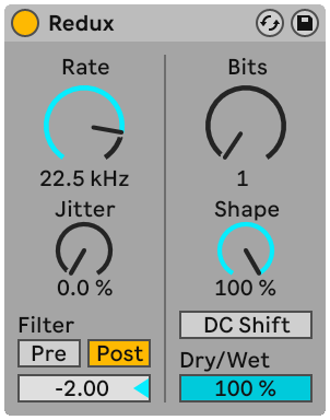
The Redux effect has a variety of parameters for creating a wide range of jagged and edgy sounds. You can radically mangle any source material, with effects ranging from harsh distortion and digital aliasing artifacts to warm, fat 8-bit grit. Extra noise and stereo width can be added to the downsampling process, while filtering further transforms the sound. The quantizer’s amplitude curve can also be changed to allow both subtle and drastic bitcrushing.
Redux makes use of two different digital signal manipulation techniques: downsampling and bit reduction.
28.30.1 Downsampling
The downsampling controls are available on the left side of the device. Using Redux’s downsampler without any filters engaged introduces inharmonic frequency content into the spectrum. The frequency range of the added content is dependent upon the relationship between the frequency content of the material and the sample rate chosen in the device.
Rate sets the sample rate to which the signal is degraded. Lower values result in increased imaging and more inharmonic tones.
Jitter adds noise to the downsampler’s clock signal, which introduces randomness to the downsampling process. This results in a noisier sound, as well as increased stereo width.
The Filter section has both a Pre and a Post setting. Enabling the Pre button engages a filter before downsampling, which reduces the bandwidth of the signal processed by downsampling. When Jitter is in use, it also reduces the stereo width of the signal.
The Post button engages a low-pass filter after the downsampling process, which reduces imaging. The Post filter frequency can be adjusted using the Post-Filter Octave slider. The number shown represents the number of octaves above or below half of the frequency shown in the Rate parameter.
28.30.2 Bit Reduction
The bit reduction controls are available on the right side of the device. Bit reduction decreases the number of bits used to represent the digital signal, reducing dynamic range while adding distortion and noise. At extreme settings, all original dynamics are lost and sounds are reduced to jagged square waves.
The Bits control reduces the number of bits being used. The value shown represents the number of bits used to encode the output signal. Reducing this value increases noise and distortion while reducing dynamic range.
Shape varies the shape of the quantizer’s characteristic curve. Higher values produce a finer resolution for smaller amplitudes, meaning that subtle signal components will be less affected than louder ones. The total amount of distortion produced with different Shape settings will depend upon the dynamic range of the input signal.
Enabling the DC Shift button applies an amplitude offset before the quantization process. This significantly changes the sound of the quantization distortion, especially when Bits is set to lower values, increasing volume and adding crunch!
The Dry/Wet control adjusts the balance between the processed and dry signals. Set it to 100% when using Redux in a return track.
28.31 Resonators
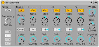
The Resonators effect consists of five parallel resonators that add a tonal character to the input signal and can be tuned in semitones or scale degrees. The effect can produce results ranging from plucked-string timbres to vocoder-like tones. It also supports tuning systems.
The input signal passes through a filter first, and then into the resonators. Four filter types are available: low-pass, band-pass, high-pass, and notch. You can use the Frequency parameter to adjust the selected filter’s frequency.
The device provides two different resonation modes. Mode A provides a more realistic sounding resonation, while Mode B offers an effect that is especially interesting when Resonator I’s Note parameter is set to lower pitches.
The Decay parameter lets you adjust the amount of time it takes for the resonators to be silent after getting an input signal. The resulting sound will be more sustained and tonal with longer decay times, similar to the behavior of an undamped piano string. As with a real string, the decay time depends on the pitch, so low notes will last longer than higher ones. The Const switch applies a constant decay time regardless of pitch.
You can adjust the brightness of the resulting sound using the Color control.
The first resonator receives both the left and right input channels, while the second and fourth resonators process the left channel, and the third and fifth process the right channel.
The tuning of the resonators depends on whether scale awareness is enabled in the effect or not, or if a tuning system is active. By default, the first resonator defines the root pitch and the other four are tuned relative to this pitch in musical intervals. When scale awareness is enabled, the first resonator is tuned relative to the active clip scale in octave 2 and the remaining resonators are tuned relative to its pitch. When a tuning system is active, the first resonator is tuned to an absolute pitch defined by the tuning, while the remaining resonators are tuned relative to its pitch.
The Note parameter sets the root pitch of all the resonators. By default, the pitch is set in semitones ranging from C-1 to C5. When scale awareness is enabled, the pitch is set in scale degrees. When a tuning system is active, the pitch is set in note indices based on the tuning system’s set of pitches. You can make fine adjustments in cents using the Resonator I Fine Tuning parameter.
All of the resonators have an On/Off toggle and a Gain control. A resonator that is turned off does not consume CPU resources. Turning off the first resonator does not affect the other ones.
Resonators II through V follow the Note parameter defined in Resonator I, but they can each be individually transposed by ±24 semitones or ±21 scale degrees (if the effect is scale aware) using their individual Pitch controls. Additional fine tuning is available through the Resonator II–V Fine Tuning parameters.
The device features the following output controls: Width, Gain, and Dry/Wet. The Width parameter only affects the wet signal and blends the output of Resonators II-V into a mono signal at 0.0%. Gain adjusts the level of the resonated signal unless Dry/Wet is set to 0%. Dry/Wet adjusts the balance between the processed and unprocessed signals.
28.32 Reverb
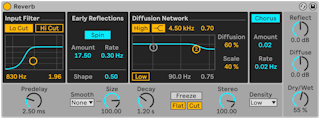
Reverb is an audio effect that simulates the acoustic properties of audio as it echoes throughout a physical space.
In the real world, reverberation exists as a product of sound waves that reflect off of rigid surfaces in an environment and the subsequent tonal shaping of these waves by absorbent materials within their trajectory. In a digital context, however, this phenomenon is approximated with a combination of filters and modulated delay lines.
The Reverb device provides granular control of all of these factors in order to create unique spaces for audio to travel through that range from intimate recording rooms to massive canyons, and everything in between.
28.32.1 Input Filter
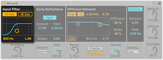
The input signal passes first through low and high cut filters, whose X-Y controller allows changing the band’s center frequency (X-axis) and bandwidth (Y-axis). The filters can also be controlled using the sliders located below the X-Y controller. Either filter may be switched off when not needed to save CPU power.
28.32.2 Early Reflections
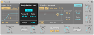
These are the earliest echoes that you hear after they bounce off a room’s walls, before the onset of the diffused reverberation tail. Their amplitude and distribution give an impression of the room’s character.
Spin applies modulation to the early reflections. The Amount and Rate sliders control the amount and rate of these modulations respectively. A higher Amount setting tends to provide a less-colored (more spectrally neutral) late diffusion response. If the modulation rate is too high, doppler frequency shifting of the source sound will occur, along with surreal panning effects. Spin may be turned off, using the associated switch, for modest CPU savings.
The Shape control sculpts the prominence of the early reflections, as well as their overlap with the diffused sound. With small values, the reflections decay more gradually and the diffused sound occurs sooner, leading to a larger overlap between these components. With large values, the reflections decay more rapidly and the diffused onset occurs later. A higher value can sometimes improve the source’s intelligibility, while a lower value may give a smoother decay.
28.32.3 Diffusion Network
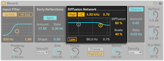
The Diffusion Network creates the reverberant tail that follows the early reflections.
High and low shelving filters provide frequency-dependent reverberation decay. The high-frequency decay models the absorption of sound energy due to air, walls and other materials in the room (people, carpeting and so forth). The low shelf provides a thinner decay. Each filter may be turned off to save CPU consumption.
The Diffusion and Scale parameters provide additional control over the diffusion’s density and coarseness, and, when the room size is extremely small, have a large impact on the coloration contributed by the diffusion.
28.32.4 Chorus
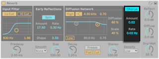
The Chorus section adds a little modulation and motion to the diffusion. You can control the modulation Amount and Rate, or deactivate it altogether.
28.32.5 Global Settings
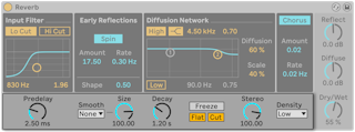
Predelay controls the delay time, in milliseconds, before the onset of the first early reflection. This delays the reverberation relative to the input signal. One’s impression of the size of a real room depends partly on this delay. Typical values for natural sounds range from 1 ms to 25 ms.
The Smooth chooser specifies the behavior of the Size parameter when its value is adjusted. If set to None, the Diffusion Network’s delay times are changed immediately, which can cause artifacts when changing the Size value. If set to Slow or Fast, new delay times are updated over a specific time period, which results in a smoother sound when transitioning between values.
The Size parameter controls the room’s volume. At one extreme, a very large size will lend a shifting, diffused delay effect to the reverb. The other extreme — a very small value — will give it a highly colored, metallic feel.
The Decay control adjusts the time required for this reverb tail to drop to 1/1000th (-60 dB) of its initial amplitude.
The Freeze control freezes the diffuse response of the input sound. When on, the reverberation will sustain almost endlessly. Flat bypasses the high and low shelf filters when Freeze is on. If Flat is off, the frozen reverberation will lose energy in the attenuated frequency bands, depending on the state of the high and low shelving filters. Cut modifies Freeze by preventing the input signal from adding to the frozen reverberation; when off, the input signal will contribute to the diffused amplitude.
The Stereo control determines the width of the output’s stereo image. At the highest setting of 120 degrees, each ear receives a reverberant channel that is independent of the other (this is also a property of the diffusion in real rooms). The lowest setting mixes the output signal to mono.
The Density chooser controls the tradeoff between reverb quality and performance. Sparse uses minimal CPU resources, while High delivers the richest reverberation.
28.32.6 Output
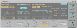
At the reverb output, you can vary the amplitude of reflections and diffusion with the Reflect and Diffuse controls and adjust the effect’s overall Dry/Wet mix.
28.33 Roar
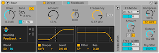
Roar is a saturation and coloration device with up to three processing stages and a range of flexible routing configurations. Its selection of non-linear shaper curves and filters can be combined to produce a wide variety of saturation types, from targeted warmth to sweeping harmonic motion or glitchy blasts of noise. Roar’s feedback controls and built-in compressor add a further layer of distinctive possibility to the device, which can produce sounds unlike any other instrument or effect currently available in Live.
28.33.1 Input Section
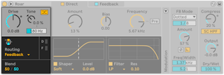
The Drive knob sets the level of the signal being input into Roar before the gain stages. It can be used to quickly add or remove distortion without having to adjust individual Shaper Amount controls across multiple gain stages, for example, or to modify an input signal to ensure a preset behaves as expected.
The Tone Amount knob changes the input signal’s balance of high and low frequencies. When set to positive values, high frequencies are boosted and low frequencies are attenuated. When set to negative values, low frequencies are boosted and high frequencies are attenuated.
The Tone Frequency slider sets the frequency of the low shelving filter used by the Tone Amount control.
Adjusting Roar’s Tone parameters has noticeable effects on the timbre of its gain stages, as these follow the Input section in Roar’s processing chain. Dialing in positive values with the Tone Amount knob can help attenuate low-frequency content in guitars or basses, for example, to avoid muddy sounds when using large amounts of distortion.
The Color Compensation toggle next to the Tone Amount control applies a mirrored version of the Tone filter to the output of Roar’s distortion stages. When active, Tone values are attenuated before the shaper and boosted after it, giving you more control over the gain stage processing. Activating the Color Compensation toggle with negative Tone values is a helpful trick for saturating drums without affecting low end frequency impact, for example.
The Routing Mode panel lets you choose from seven routing types: Single, Serial, Parallel, Multi Band, Mid Side, Feedback, and Delay. Apart from Single and Multi Band, each routing mode comes with the Blend control that you can use to control the blend between its two gain stages.
The Serial routing mode processes the input signal using two concatenated shapers. The Blend control blends between the sound of Stage 1 and the sound of Stages 1 and 2 combined.
The Parallel mode processes the input signal using two independent shapers. The Blend control blends between the sound of Stage 1 and the sound of Stage 2. To experiment with this mode, try selecting two noticeably different Shaper Curves (like Half Wave Rectifier and Fractal) and modulating the Blend control so that Roar’s sound shifts continuously from one to the other.
Multi Band splits the frequency spectrum into three bands (Low, Mid, and High) that can each be processed independently. Two Crossover Filters (Low and High) let you define the crossover frequency between the three bands. This mode serves a variety of applications, including drum processing and adding saturation to entire mixes.
Mid Side processes the input signal’s mono and stereo signals independently. This mode is useful for enhancing a signal’s stereo image without compromising the sound of the signal at the center of the stereo field.
The Feedback routing mode processes the input signal and its feedback independently, which can create unusual tones or transform Roar into a distinctive delay. Try modulating Roar’s Shaper Amount with an envelope to produce saturation that has a shuffled delay effect, for example, or subtly offsetting Shaper Bias to create delays that degrade over time.
In the Delay mode, the second stage processes the delayed signal from the first stage. The delayed signal is sent to the second stage without being scaled by the feedback gain, which produces single (distorted) repetitions or slapbacks. The output of the second stage is fed back into itself and scaled with the feedback gain, resulting in multiple repetitions and long signal tails.
28.33.2 Gain Stage Section
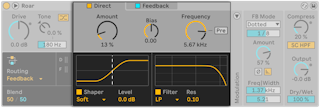
Each routing mode has its own set of gain stages, which can be turned on or off independently using the Stage toggles in the Gain Stage tabs.
Gain Stage tabs all have the same three controls: Shaper Amount, Shaper Bias, and Filter Frequency. Shaper and Filter Types can be selected from their corresponding drop-down menus at the bottom of each Gain Stage tab.
The Shaper Amount control sets the amount of saturation applied to the input signal. You can also click and drag the shaper waveform in the Shaper Visualization display to modify this parameter. Distortion occurs when the input signal reaches non-linear portions of the visualized curve.
The Shaper Bias control offsets the signal and creates asymmetrical distortion. At higher settings, it can emulate the sound of a broken circuit. At more extreme settings, it will cause the signal to go completely quiet.
The Shaper Type drop-down menu under the Shaper Visualization display has twelve curves to choose from:
Soft Sine uses a sinusoidal curve to add smooth, warm saturation to the input signal. This shaper curve tends to produce pleasant, analog-style distortion even when pushed to extreme levels.
Digital Clip applies a hard clipping curve to the input signal. It produces harsh, higher-order harmonics when the input signal reaches the curve’s extremities.
Bit Crusher produces the characteristic distortion that occurs when quantized amplitudes are applied to an input signal, similar to Live’s Redux device. Increasing the Shaper Amount reduces the number of bits used for quantization and intensifies the effects of the bit crusher’s built-in compander. This curve works well with bias modulation and produces very obvious changes in quieter signals.
Diode Clipper this type is a virtual analog clipping circuit emulation. It sounds smooth and warm like the Soft Sine curve, but with attenuated high-end frequencies.
Tube Preamp models the soft, analog saturation of a tube preamp. It preserves a signal’s transients and dynamics even when the Shaper Amount is set to higher levels.
Half Wave Rectifier and Full Wave Rectifier produce distinctive, waveshaper-style effects. Half Wave Rectifier applies completely asymmetrical distortion to the input signal, which works well for adding crunch to drum sounds. Full Wave Rectifier shifts the signal up by an octave, which works well for adding harmonic depth to certain synth sounds.
Polynomial shifts between a sinusoidal curve and more complex waveforms. This shaper curve lends itself well to modulation and to producing metallic sounds.
Fractal introduces a large of amount of high-end harmonics to the input signal.
Tri Fold this type is a triangular wavefolder. Like Fractal, it adds a large amount of high-end harmonics to the input but achieves even harsher, more distorted results.
Noise Injection applies stereo noise followed by smooth distortion to the input signal. This curve works well for producing smooth saturation that also has some dirt and grit.
Shards continuously changes the slope of its stereo curve segments to rhythmically break apart the input signal.
Shapers can also be turned on or off via the toggle at the bottom of the Shaper Visualization display.
The Shaper Level control can be used to compensate for changes in output level produced as the shaper curve is modified.
Filter Frequency adjusts the filter’s cutoff frequency. If the Pre toggle has been activated, the filter is applied before the Shaper stage. When the Filter Frequency is changed with Pre activated, the filter doesn’t affect the harmonics produced by the shaper.
There are nine filter types to choose from: LP (low-pass), BP (band-pass), HP (high-pass), Notch, Peak, Morph, Comb, Resampling, and Dispersion.
The LP filter attenuates frequencies above the cutoff, BP attenuates lower and higher frequencies outside of a specific range, while HP attenuates frequencies below the cutoff.
Notch attenuates a narrow frequency range while leaving the surrounding frequencies largely unaffected.
The Morph filter allows continuous morphing between low-pass and high-pass filtering, with band-pass behavior in between.
Comb creates a series of notches across the frequency spectrum. When its cutoff is modulated, this filter type can produce flanger-like effects.
The Resampling filter produces sample-rate reduction artifacts, similar to Live’s Redux device.
Dispersion shifts different frequencies in time by different amounts, without changing their level. This slight misalignment of frequencies can create metallic, spring-like tones, especially when modulated.
Apart from the Resampling filter, each filter has a dedicated Resonance control. The Peak filter has a Filter Peak Gain control for boosting or attenuating a specific frequency range. The Morph filter has a Morph control for setting its filter shape.
28.33.3 Modulation Section
To display Roar’s modulation parameters, click on the toggle in the Modulation panel. This will bring up the Mod Sources and Matrix tabs.
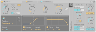
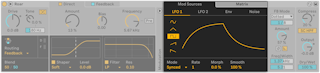
The Mod Sources tab has four modulation sources to choose from: LFO 1, LFO 2, Env (Envelope), and Noise. Each of the modulation sources comes with a display that visualizes the signal, as well as a set of distinct parameters.
You can choose one of five waveforms for each LFO: sine, triangle, square, up, or down.
The LFO rate mode can be set to Free, Synced, Triplet, Dotted, or Sixteenth using the Mode chooser. The LFO rate is set via the Rate slider in Hertz (in the Free mode) or tempo-synced beat divisions (in the other modes). The Morph control’s value can be set manually or modulated to further sculpt the LFO shape. The Smooth control allows you to add smoothing to the LFO signal, which can be helpful in preventing harsh changes while using modulation.
The Env tab’s envelope follower generates a modulation signal based on Roar’s input signal. You can use the parameters in this tab to adjust the envelope follower’s response to the input signal.
The Attack and Release controls shape how quickly the envelope responds to the input signal. You can also use the Envelope Hold toggle to control how the envelope moves from the attack to release phase: when on, the envelope completes the entire attack phase before starting the release phase.
The Threshold and Gain controls set the envelope’s sensitivity and strength, while Frequency and Width allow you to set a specific frequency range for the signal fed into the envelope follower.
To play back the input signal only, activate the Envelope Input Listen toggle.
The envelope follower is particularly useful as a modulation source in Roar’s Modulation Matrix. Try setting it to follow a snare sound in a drum loop, for example, and have it modulate Roar’s Dry/Wet balance or Shaper Amount each time the snare hits.
The Noise modulation source includes four different noise types: Simplex, Wander, S & H, and Brown. Noise curves can be set in Hertz or tempo-synced and can be smoothed like Roar’s LFO curves.
Simplex and Wander both generate smoothed random signals, with different random value interpolation algorithms used to produce different signal dynamics. Simplex uses interrate modulation, which produces a more irregular value interval than Wander. These types of noise are useful for introducing small, random, organic-style changes in Roar’s output signal, especially when set to low rates.
S & H (Sample and Hold) generates a random constant value that changes to a new random value at an interval determined by the Noise Rate. This is useful for creating stepped random modulation patterns in Roar’s output signal.
Brown produces low-pass filtered white noise, which is useful for producing a constant noise floor or for adding crackles and hissing to Roar’s output signal.
The Matrix tab lets you assign modulation sources to modulation targets within the device. Clicking a parameter while the Matrix tab is open will set it as a modulation target. Modulation sources are listed horizontally and modulation targets are listed vertically. Click and drag a cell up or down to apply modulation between parameters.
The Global Modulation Amount slider can be dragged up or down to increase or decrease the modulation being applied globally. Clicking the X button will erase all modulation applied by the Modulation Matrix.
The Modulation Matrix can also be expanded using the toggle in the device header. When expanded, the device’s gain stages are all visible at once, as are all of the modulation sources and targets in the Modulation Matrix.
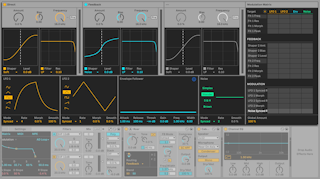
Apart from the visualization displays, modulation signals are also indicated via LEDs in the Modulation column. Each LED uses a color that corresponds to a modulation source. This allows you to quickly determine whether a modulation source is active and gives you an idea of how the source is set up without needing to dive into the Modulation Matrix.
28.33.4 Feedback Section
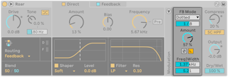
The Feedback section is one of Roar’s most distinctive features. Feeding Roar’s signal back into itself can add a new layer of ringing, otherworldly tones and textures to your sound.
The Feedback Mode drop-down lets you choose between five feedback modes: Time, Synced, Triplet, Dotted, and Note. Synced and Time modes let you use Roar’s Feedback as a delay. Note mode lets you set the feedback’s ring to a specific pitch.
The Feedback Amount knob sets the amount of signal being fed back into Roar’s input. Because a compressor is present in Roar’s feedback loop, loud signals will temporarily attenuate the amount of feedback being generated as gain reduction is applied by the compressor.
When the Feedback Invert toggle is turned on, the phase of Roar’s feedback signal is inverted. The phase cancelation effect that occurs when this inverted signal is fed back into the original creates another layer to experiment with in Roar’s processing chain.
When the Feedback Gate toggle is turned on, Roar’s feedback automatically fades out when an input signal is no longer being sent into the device. When turned off, Roar’s feedback continues indefinitely.
The Feedback Filter Frequency slider sets the center frequency of the band-pass filter used to process Roar’s feedback. The Feedback Filter Width slider adjusts the filter’s bandwidth.
28.33.5 Global Section
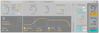
The Compression Amount knob sets the amount of compression being applied to the output signal, and thereby to the signal being fed back into Roar.
When the Compressor Sidechain HP Filter toggle is turned on, a high-pass filter is applied to the analysis signal used by the compressor’s sidechain. This is useful for lowering the amount of gain reduction generated by the compressor’s response to low frequency signals.
The Output Gain knob sets the level of the wet signal being output, which is followed by a hard clipping stage and then fed into the Dry/Wet stage. This parameter is useful for compensating level changes produced by the Drive or Shaper Amount knobs.
The Dry/Wet slider adjusts the balance between the dry and wet signal being output by Roar.
28.33.6 Sidechain Parameters
By default, Roar uses its input signal to drive its envelope follower and set its feedback pitch. The Sidechain section allows you to use external audio and MIDI signals instead. To access the external and MIDI sidechain parameters, click on the Sidechain Section toggle in the upper left corner of the device.

Switch on the External SC toggle to enable the external sidechain. Once enabled, you can specify the source of the signal with the External Source chooser. You can also choose whether the signal should be received Post FX or Post Mixer via the External Tapping Point chooser.
The Mix slider allows you to use a combination of the external and internal sidechain signals as the envelope follower’s trigger. At 100%, the envelope follower tracks the external sidechain source exclusively. At 0%, only the internal sidechain is used.
You can use the SC Gain control to adjust the level of the external sidechain’s input. Note that the sidechain audio is only a trigger for the envelope follower, so increasing the gain does not increase the volume of the source signal.
Switch on the MIDI > FB Note toggle to use MIDI input for setting the pitch used by Roar’s feedback mechanism when the feedback mode is set to Note. Once MIDI sidechain is enabled, use the External Source chooser under MIDI From to specify the MIDI sidechain source. You can also choose whether the signal should be received Pre FX or Post FX via the Tapping Point chooser.
Note that the Feedback Mode and Feedback Amount controls in the feedback section are inactive when the MIDI sidechain is active.
To monitor the sidechain signal, enable the Sidechain Listen toggle. This bypasses Roar’s output and lets you hear the sidechain input directly, which can be useful when adjusting sidechain parameters.

28.34 Saturator
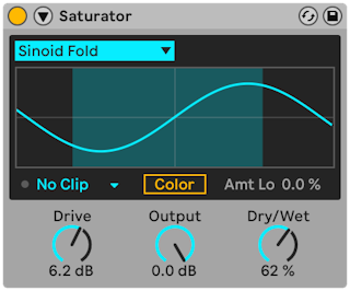
Saturator is a waveshaping effect that can add that missing dirt, punch or warmth to your sound. It works by applying non-linear shaping to the input signal, with results ranging from soft saturation to intense coloration.
Saturator shapes the incoming signal by mapping each individual value in the signal to a new value according to a selected shaping curve. Because this is usually a non-linear process, the incoming signal is dynamically reshaped based on its level at each moment in time.
You can select the curve used for shaping the input signal from the Curve Type chooser. There are eight types to choose from: Analog Clip, Soft Sine, Bass Shaper, Medium Curve, Hard Curve, Sinoid Fold, Digital Clip, and Waveshaper.
The available curve types offer various shaping characteristics. Digital Clip applies immediate, hard clipping when exceeding the clipping point, while Analog Clip introduces a smoother transition around the clipping point. These curves remain linear for signal levels below the clipping point. The Soft Sine, Medium Curve, and Hard Curve types apply saturation with different sonic characteristic. Sinoid Fold is a wavefolding type — as the input signal gets louder, the output folds over itself, producing unusual textures.
The Bass Shaper curve is somewhat similar to Analog Clip, but presents a smoother harmonic spectrum when driving low frequency signals with high gain. This makes it ideal for processing low-end signals like 808 kick drums and synth basslines.
Bass Shaper includes an additional Bass Shaper Threshold control, which sets the threshold for the curve from 0 to -50 dB. The curve remains linear when the input signal is below the threshold but smoothly starts to clip once the signal exceeds the threshold. This allows you to move continuously from one form of clipping to another: low threshold values produce soft clipping and high threshold values produce hard clipping. Low threshold values work best for bass signals, especially when combined with high Drive values.
The most dramatic signal shaping effect can be created by selecting the Waveshaper curve. This type has its own dedicated set of controls, which are accessible by clicking the Toggle Expanded View button in the device title bar; you can read more about how these parameters affect the signal in the dedicated section below.
The Shaper Curve display both helps to visualize Saturator’s shaping curve and shows the input signal in relation to the selected curve type in real time. Saturation occurs when the input signal reaches the non-linear sections of the curve.
You can select a post-clipping stage for all the curve types using the Post Clip Mode chooser below the Shaper Curve display. When Soft Clip or Hard Clip is selected, Saturator’s output will never exceed the level set by the Output control. This is particularly useful for controlling any additional boost created by negative Color values.
The Color toggle enables the device’s two color filters, which produce a color curve visualized in the device’s expanded view. The color filters adjust an EQ curve that is first applied before the shaper, then applied again, inverted, after the shaper. This allows you to, for example, remove bass frequencies before the shaper, so that only mid/high frequencies are saturated and the energy of the bass is maintained in the output.
You can use the Amt Lo slider to adjust the amount of saturation applied to low frequencies. Negative values reduce the overall saturation applied to low frequencies, while positive values increase it.
The Drive control adjusts the gain applied to the input signal before it is processed by Saturator. You can see how much this parameter is affecting the input signal in the device’s Shaper Curve display.
The Output control attenuates the signal level of Saturator’s final output. When Soft Clip is activated in the Post Clip Mode chooser, Saturator will also apply an instance of the Analog Clip curve to the device’s output.
The Dry/Wet control sets the balance between dry and processed signals in Saturator’s output. Set it to 100% when using Saturator in a return track.
The Color Curve display in the expanded view shows a visualization of the curve being applied by the device’s two color filters.
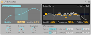
Below the display, there are three more controls for shaping Saturator’s color filters. Use the Amt Hi slider to adjust the amount of saturation applied to the specified frequency range via the second filter. Positive values add more saturation, while negative values decrease it. The Frequency slider can be used to adjust the center frequency affected by the second color filter, while Width determines the overall range of frequencies affected by it.
You can adjust the color filter parameters by clicking and dragging the handles in the Color Curve display — dragging the first handle adjusts the Amt Lo parameter, while dragging the second handle adjusts the Amt Hi or Frequency parameters, depending on whether you’re dragging the handle horizontally or vertically.
28.34.0.1 Saturator’s Waveshaper Controls
When you select the Waveshaper curve type, six additional parameters become active in the expanded view.
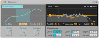
The Waveshaper controls influence the device’s signal shaping functions in the following ways:
- Drive determines how much the Waveshaper curve’s parameters affect the input signal. At 0%, these parameters have no effect on the Waveshaper curve. At 100%, these parameters fully shape the curve.
- Curve adds mostly third-order harmonics to the input signal.
- Depth controls the amplitude of a sine wave that is superimposed onto the Waveshaper curve. Increasing the value raises the amplitude of the sine wave, making its effect on the shaping curve more pronounced. At 0%, the sine wave has no influence.
- Linear works with the Curve and Depth parameters to alter the linear portion of the Waveshaper curve.
- Damp flattens any signals near the center of the waveform. It functions like an ultra-fast noise gate.
- Period determines the density of ripples in the superimposed sine wave in relation to the Depth control.
28.34.0.2 Context Menu Options for Saturator
Two additional modes can be enabled in Saturator’s context menu: Hi-Quality and Pre-DC Filter. The Hi-Quality mode reduces aliasing and improves sound quality (especially with high frequency signals), at the cost of a slight increase in CPU usage. The Pre-DC Filter mode activates a DC filter at Saturator’s input stage, which is useful for removing DC offsets from audio that contains them.
28.35 Shifter
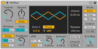
Shifter is a multi-purpose pitch and frequency-shifting audio effect that can be used to add ring modulation to incoming audio or to shift the pitch or frequency of audio in real time.
28.35.1 Tuning and Delay Section
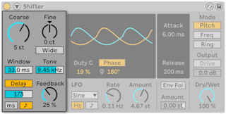
The Coarse and Fine knobs adjust the pitch or frequency in the given value, depending on which shift mode (explained in the Shifter Mode section) is selected.
Enabling the Wide button inverts the polarity of the Spread value for the right channel, creating a stereo effect. This means that increasing the Spread value will shift the frequency down in the right channel while shifting it up in the left. Note that Wide has no effect if the Spread value is set to 0.
In Pitch mode, the Window slider adjusts the window size used by the algorithm. Low frequency signals often sound best with longer window sizes, while high frequencies often sound best with shorter window sizes. Tone cuts the high frequencies of the delay’s feedback path.
Enabling the Delay button adds delay time that can be set using the slider control in Hertz or beat-synced divisions, depending on which Delay Mode button you select. The Delay Feedback knob sets the amount of the output that is fed back to the input of the delay.
28.35.2 LFO Section
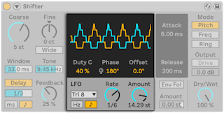
You can modulate the left and right stereo channels using Shifter’s LFO.
In the LFO waveform display, you can set the Duty Cycle and Phase/Spin/Width controls. Duty Cycle sets the duty cycle of the LFO waveform. Phase adjusts the offset between the waveforms for the left and right channel. At 180° the LFOs will be perfectly out of phase. Depending on the LFO waveform or the Rate parameter, Phase may be replaced by a Spin or Width control, as explained below.
When the Rate parameter (as described in further detail below) is set to beat-synced time divisions, you will see the Offset parameter next to the Phase parameter, which shifts the starting point of each LFO along its waveform.
There are several different LFO waveforms to choose from the LFO drop-down menu: Sine, Triangle, Triangle Analog, Triangle 8, Triangle 16, Saw Up, Saw Down, Rectangle, Random, and Random S&H.
The LFO waveforms Sine, Triangle, Triangle Analog, Triangle 8, Triangle 16, Saw Up, Saw Down, and Rectangle can also be set to Spin instead of Phase. Spin detunes the two LFO speeds relative to one another.
The LFO waveforms Random and Random S&H can only be set to Phase and Width, respectively. Width adjusts the Stereo width of the random LFO waveform. At 0%, the waveform is identical for the left and right channels. At 100%, the waveform is fully stereo, peaks on the left will correspond to valleys on the right and vice versa.
LFO modulation is controlled with the Rate parameter, which can be set in Hertz or synced to the song tempo and set in meter subdivisions (e.g. sixteenth notes). The Amount parameter sets the amount of LFO modulation that is applied to incoming signals.
28.35.3 Envelope Follower Section
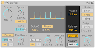
Shifter’s envelope follower uses the amplitude from an incoming audio signal and translates it to a modulation source.
The Envelope Attack sets how quickly the envelope follower responds to rising input levels and the Envelope Release sets how quickly the envelope follower responds to falling input levels.
The Env Fol button switches on Shifter’s envelope follower. The Amount adjusts the intensity of the envelope follower’s modulation. The Amount value can be set in semitones in Pitch mode or in Hertz in the Freq and Ring modes.
28.35.4 Shifter Mode Section
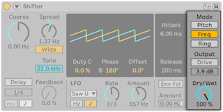
Three different Shifter Mode button switches are available: Pitch, Freq, and Ring.
Pitch mode adjusts the pitch of incoming audio up or down by a user-specified amount in semitones (Coarse tuning) and cents (Fine tuning).
Freq mode moves the frequencies of incoming audio up or down by a user-specified amount in Hertz. Small amounts of shift can result in subtle tremolo or phasing effects, while large shifts can create dissonant, metallic sounds.
In Ring mode, the user-specified frequency amount in Hertz is added to and subtracted from the input.
Drive enables a distortion effect, and the slider below it controls the level of the distortion. Note: Drive is only available in Ring mode.
The Dry/Wet knob sets the balance between the dry and processed signals at Shifter’s output.
28.35.5 Sidechain Parameters
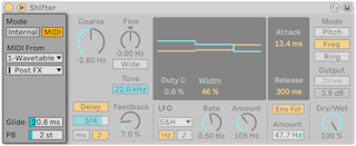
To access the Sidechain parameters, unfold the Shifter window by toggling the triangle button on the left of the title bar. There are two Pitch Modes available that determine how the pitch or frequency is set: Internal and MIDI. In Internal mode, the pitch or frequency is set by Shifter’s Coarse and Fine knobs. In MIDI mode, the pitch or frequency is set by an incoming MIDI note.
In MIDI mode, you will see a drop-down menu where you can select an external MIDI source. There is also a Glide parameter that adjusts the time in milliseconds over which it takes notes to slide their pitch to the next incoming pitch. You can set a pitch bend range between 0-24 semitones to define the effect of MIDI pitch bend messages using the PB slider.
28.35.6 Shifter Tips
28.35.6.1 Pitch-shifted Drum Layers
To add glitchy, metallic echoes to a drum loop, duplicate your drum track and add Shifter after the Drum Rack. In Pitch mode, try adjusting or automating the Coarse knob and enable the Delay button. Higher pitch shifts will create a metallic and crisp echoed delay. Lower pitch shifts will create a drawn-out delay effect. You can lower the volume of the pitch-shifted track so that it sits in the background, adding some movement to the main drum track.
28.35.6.2 Phasing Effects
To create lush phasing effects, minimally adjust (no more than 2 Hz or so) the Fine knob in Freq mode. Phasing is caused by the interaction of the processed and dry signals; you can adjust the Mix balance so that both are audible. The strongest phasing will be heard when MIx is at 50%.
28.35.6.3 Tremolo Effects
In Ring mode, frequencies below the audible range (about 20 Hz or slightly lower) create a tremolo effect. You can also impart a sense of stereo motion to the tremolo by turning on Wide and using small Spread values.
28.36 Spectral Resonator
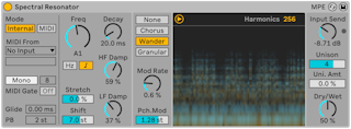
Spectral Resonator transforms an audio signal by applying tuned resonances to its spectrum. You can highlight chosen frequencies of the resonating partials and alter their decay, creating either short percussive reverberations or long washed-out tones. Choose which frequencies are affected through an internal resonator or via an external MIDI sidechain. Similar to a vocoder, you can use the MIDI input to place the resonances in key with its surrounding musical elements, playing the effect polyphonically with up to 16 voices. You can shape the signal further with different modulation modes to add movement and depth or create more fragmented, textural results. The effect also supports scale awareness and tuning systems.
28.36.1 Pitch Mode Section

Spectral Resonator offers two modes that determine how the fundamental pitch of the effect’s resonant harmonics is set: Internal or MIDI.
When the Internal mode is enabled, the device is fixed to a single pitch, while in the MIDI mode the resonator is tuned dynamically according to external note input. Additional controls become available when MIDI mode is enabled:
- External Source and Tapping Point let you select any MIDI track as the input source and choose whether the signal is taken before or after MIDI effects in the track’s device chain. To use an external MIDI controller, select it in the Input Type chooser on a MIDI track, then select that track in Spectral Resonator’s External Source chooser.
- The Mono/Poly toggle switches between single and polyphonic voice modes. When set to Poly, Spectral Resonator can receive polyphonic material such as chords.
- The Polyphony slider sets the number of voices the effect uses, from 2 to 16.
- The MIDI Gate toggle determines how the resonator is activated. When set to On, the device functions more like an instrument and will only resonate only while MIDI notes are played. When set to Off, the resonator still responds to audio input, even without incoming notes. Note that MIDI Gate is always active in Poly mode.
- Glide adjusts the time it takes for pitch to slide between consecutive notes, in milliseconds. Note that the parameter is only active in Mono mode.
- PB sets how much MIDI pitch bend messages shift the resonator’s pitch, from 0-24 semitones. Note that Spectral Resonator is also able to receive MPE data.
28.36.2 Frequency Section

When the Internal pitch mode is enabled, Spectral Resonator is tuned to the frequency set by the Freq control. You can adjust the frequency in Hertz or set it to a specific pitch; to toggle between the two options, use the Frequency Control Mode buttons below the Freq control. If the Use Current Scale toggle is on, the device follows the active clip scale instead. The control becomes SD Shift and can be used to transpose the resonator in scale degrees. Note that if scale awareness is enabled but no scale is active, Spectral Resonator follows the chromatic scale.
When the MIDI mode is enabled, Spectral Resonator is tuned to the frequencies of incoming MIDI notes. The MIDI input can be transposed by ±48 semitones using the Transp. control or by ±28 scale degrees when Use Current Scale is on. When the effect is scale aware, Transp. becomes the SD Shift control.
Spectral Resonator works with tuning systems in both modes. When a tuning system is active, the Freq control in Internal mode and Transp. control in MIDI mode use note indices instead of note names and semitones, respectively.
You can use the Stretch slider to adjust the spacing between the resonant harmonics. Values below 0% compress the distance, while values above 0 expand it. At 100%, only odd harmonics are produced, which leads to a square-wave type sound.
The Shift slider transposes the spectrum of the input signal by ±48 semitones. Note that this affects the signal fed into the device and not the resonator’s own spectrum.
The Decay control sets how long the resonances persist. Higher values produce longer, sustained tones.
HF Damp sets the amount of damping applied to high-frequency partials, while LF Damp sets the amount of damping applied to low-frequency partials. In both cases, the affected frequency ranges shift according to the current pitch (when in Internal mode) or the pitch of the incoming MIDI notes (when in MIDI mode).
28.36.3 Modulation Section

You can set the effect to one of four modulation modes using the respective toggles: None, Chorus, Wander, or Granular. These modes determine how each harmonic’s pitch and amplitude are modulated:
- None applies no modulation.
- Chorus applies triangle wave modulation to each partial. When Mod Rate is set to 0, this mode only modulates the amplitudes of the partials.
- Wander uses random sawtooth waveforms as the modulation source for each partial.
- Granular modulates the amplitude of all partials randomly, using exponential decay envelopes. Partials are generated at irregular intervals, and the Mod Rate parameter affects their density.
All modulation modes are also affected by the Mod Rate and Pch. Mod controls. Mod Rate sets the modulation rate, while Pch. Mod adjusts the range of pitch modulation in semitones. Although Pch. Mod displays only a positive value, pitch modulation is bipolar in all modes except Granular, where the grain envelopes are only applied in a positive direction.
28.36.4 Spectrogram

Spectral Resonator includes a spectrogram that displays the activity of frequencies in the dry and wet signals over time. Dry signals are shown in yellow and wet signals in blue. You can hide the spectrogram using the toggle in the upper-left corner of the display. The visualization helps identify which regions of the spectrum are being emphasized or modified by the resonator.
Two controls are integrated into the spectrogram display: Harmonics and Quantize. You can use Harmonics to set the number of resonant harmonics used by the device. Higher values create a brighter sound, while lower values produce a darker timbre. Note that when using polyphony, the number of harmonics is evenly distributed between the voices, resulting in fewer harmonics per voice when high voice counts are used. Increasing harmonics also increases CPU usage.
When Quantize is enabled, each harmonic is quantized to the active scale or tuning system. If no scale or tuning system is active, the harmonics are quantized to chromatic pitches instead.
28.36.5 Global Parameters

The Input Send control sets the amount of gain applied to the processed signal. A built-in limiter prevents the signal from clipping. The LED next to Input Send will light up when the limiter is in use.
The Unison parameter sets the number of unison voices, which are detuned copies of the resonator’s partials. Use the Uni. Amt parameter to adjust the amount of detuning between those voices. Increasing the number of voices thickens the sound, while higher detuning values create a wider and more animated character. In the Wander and Granular modulation modes, each voice is modulated independently, creating especially dense and warbly textures.
The Dry/Wet control adjusts the balance between the processed and unprocessed signals, and affects how prominently each signal appears in the spectrogram. Set Dry/Wet to 100% when using Spectral Resonator in a return track.
28.36.6 Spectral Resonator Tips
Here are some ways you can use Spectral Resonator in your projects:
- Create tonal drum loops by placing Spectral Resonator on a drum track and using the MIDI sidechain input to drive specific pitches. This can be used to add rhythm to your track, allowing the drum material to align tonally with other elements such as the bassline.
- Set up Spectral Resonator to follow melodic pitches by first converting audio to MIDI with Convert Harmony to New MIDI Track or Convert Melody to New MIDI Track, then routing the generated MIDI track into the effect.
- Create reverb-like sounds by setting Freq to a low value, increasing Unison and Uni. Amt values, and using the Wander modulation mode in combination with low Mod Rate and Pch. Mod values. Adjust the Decay parameter to control the “reverb” decay.
- Use Spectral Resonator like a vocoder by placing the effect on a vocal track and controlling it via MIDI sidechain input.
- Layer harmonics by placing two Spectral Resonators in series and sending different MIDI signals to each one to create overlapping resonant structures.
28.37 Spectral Time
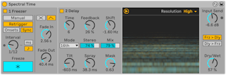
Spectral Time combines time freezing and spectral delay effects in a single inspiring device. You can resynthesize your sounds by applying various spectral filters, delays and frequency-shifting techniques to incoming material, creating highly varied and unique copies. The freeze and delay effects can be used together or independently, allowing for a wide range of possibilities, such as sustaining any sound infinitely, or combining delays with time-synced fade transitions. You can easily transform sounds by smearing frequencies over time, or add metallic echoes and space to any sound source.
Spectral Time has two main sections, Freezer and Delay, which can be used individually or serially, with the freezer feeding the delay. You can toggle the individual sections using the Freezer On and Delay On buttons.
Spectral Time uses a spectrogram to display how frequencies in the dry and wet signals behave over time. Dry signals are represented in yellow, while wet signals are shown in blue. You can hide the visualization by clicking on its toggle button.
From Spectral Time’s context menu, you can switch Zero Dry Signal Latency on or off. Enabling it reduces the latency of the dry signal to zero instead of syncing it with the output of the effect. This option is useful when playing a live instrument through Spectral Time and monitoring the output.
28.37.1 Freezer Section
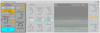
Depending on which of the Manual/Retrigger Mode buttons are activated, the Freezer section controls how the freeze function is triggered and how certain temporal characteristics of the frozen audio are affected. Note that for both modes, the Freeze button also has to be toggled in order for the effect to occur.
In Manual mode, audio can be frozen by clicking on the Freeze button. You can also control the Fade In and Fade Out time of the frozen signal in milliseconds.
In Retrigger mode, you have more controls to fine-tune the rhythm of the frozen audio, which can be frozen automatically at every transient (onset), or at regular intervals.
Onsets mode will freeze the audio after a transient is detected in the input. Use the Sensitivity knob to adjust the sensitivity of onset detection. Sensitivity is highest at 100% and lowest at 0%.
Sync mode will freeze the audio at regular intervals, determined by the Interval control. By toggling the Freezer Time Unit buttons, the Interval control can be set to either milliseconds or beat-time values.
In both Onsets and Sync modes, the Freezer Fade Shape buttons toggle between two available fade shapes: Crossfade and Envelope. Both fade shapes have different controls to determine how a new freeze will fade in and out.
When the Crossfade shape is selected, the new freeze will fade in and the old freeze (or dry signal) will fade out. The crossfade duration is set by the X-Fade control, which specifically determines the time in milliseconds over which a new freeze will fade in as a percentage of the sync interval set by the Interval control.
When the Envelope shape is selected, a new freeze will fade in and out according to the millisecond time values chosen in the Fade In and Fade Out parameters. In this mode, up to eight simultaneous freezes can be stacked on top of one another.
28.37.2 Delay Section
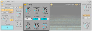
The Delay section of Spectral Time can be activated or deactivated with the Delay toggle button and allows you to create delayed copies of spectral information. If the Freezer section is enabled, the Delay section will be fed by the Freezer’s output.
The Time parameter controls the delay time for the spectral delay lines. The type of value shown here is dependent on the unit type chosen in the “Mode” drop-down chooser:
- Time mode adjusts the delay time in milliseconds.
- Notes adjusts delay time in beat divisions.
- 16th, 16th Triplet, and 16th Dotted set the delay time to the number of the chosen type of 16th notes.
Feedback sets the amount of output that is fed back to the delay input. Turning this up increases the audible echoes of the signal.
Shift shifts the frequency of the delayed signals. Each successive delay will be shifted up or down by the specified frequency amount.
Stereo adjusts the width of the Tilt and Spray controls.
The Dry/Wet control adjusts the balance between the delayed and dry signals. Note that this only affects the Delay section of the device.
Tilt skews the delay times for different frequencies. A positive value will delay high frequencies more than low frequencies, while a negative value delays low frequencies more than high frequencies.
Spray distributes the delay times for different frequencies randomly within the given time range.
Mask limits the effects of the Tilt and Spray controls to either high or low frequencies. Positive values limit the effects to high frequencies, while negative values limit the effects to low frequencies.
28.37.3 Resolution Section
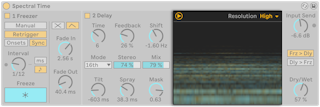
In the upper right corner of the spectrogram display, you will find the Resolution control, which sets the resolution used to process the incoming signal. Lower values reduce the overall latency at the cost of accuracy and fidelity. Note that since higher values affect overall latency, you may wish to reduce the Resolution while tracking.
28.37.4 Global Controls
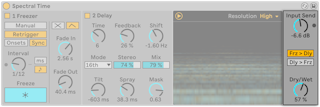
Input Send adjusts the gain of the input signal.
The two radio buttons Frz > Dly and Dly > Frz reverse the effect order.
The global Dry/Wet control adjusts the balance between the processed and dry signals. Set it to 100% when using Spectral Time in a return track.
28.38 Spectrum
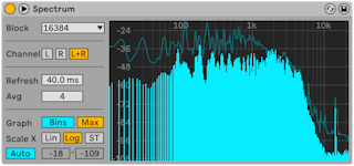
Spectrum performs real-time frequency analysis of incoming audio signals. The results are represented in a graph, with dB along the vertical axis and frequency/pitch along the horizontal. The peak levels are retained on the graph until the song is restarted. Note that Spectrum is not an audio effect, but rather a measurement tool — it does not alter the incoming signal in any way.
The Block chooser selects the number of samples that will be analyzed in each measurement. Higher values result in better accuracy, but at the expense of increased CPU load.
Channel determines which channel is analyzed — left, right or both.
The Refresh slider determines how often Spectrum should perform an analysis. As with the Block parameter, this allows for a tradeoff between accuracy and CPU load. A fast response time is more accurate, but also more CPU intensive.
The Avg slider allows you to specify how many blocks of samples will be averaged for each update of the display. With a setting of one, each block is shown. This results in much more activity in the display, which can be useful for finding the spectrum of short peaks. As you increase the Avg value, the display updates more smoothly, providing an average of the spectrum over time. This is more consistent with the way we actually hear.
The Graph button switches between displaying the spectrum as a single interpolated line and discrete frequency bins.
Max toggles the display of the accumulated maximum amplitude. With Max enabled, you can reset the maximum amplitude by clicking in the display.
The Scale X buttons allow you to toggle the scaling of the frequency display between linear, logarithmic, and semitone. Note that logarithmic and semitone are actually the same scaling, but switch the legending at the top of the display between Hertz and note names. Linear scaling is particularly useful for detailed analysis of high frequencies.
As you move your mouse over Spectrum’s display, a box appears that shows the amplitude, frequency and note name at the pointer’s position. The Range/Auto button at the bottom left of Spectrum’s interface toggles between manually and automatically adjusting the display’s dynamic range. With Range selected, you can zoom and scroll the amplitude by moving your mouse over the amplitude legending on the display’s left side. Drag vertically to scroll and horizontally to zoom. You can also use the Range sliders to set the minimum and maximum amplitude values shown. With Auto selected, the display automatically scales itself based on the incoming audio level. Note that in Auto mode, the Range sliders and zooming are disabled.
To get an even better view, you can toggle the location of the display between the device chain and Live’s main window by clicking the button in Spectrum’s title bar or by double-clicking in the display.
28.39 Tuner
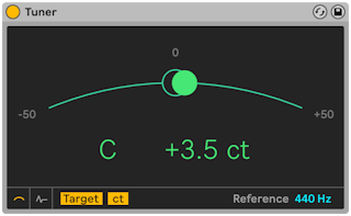
Tuner analyzes and displays the incoming monophonic pitch as well as its distance from the nearest semitone. Based on classic guitar tuners, Tuner’s large display is designed for easy visibility on stage, and is perfect for tuning external instruments or synthesizers.
It is important to note that Tuner is not an audio effect, but rather a measurement tool – it does not alter the incoming signal in any way. Tuner is designed to analyze monophonic pitches, and works best with a clean, clear signal. Polyphonic, noisy, or harmonically rich signals may yield inaccurate results.
28.39.1 View Switches
The two buttons in the lower-left switch between Tuner’s two main views. Classic View resembles conventional analog tuners while Histogram View shows pitch over time. In both views, the display uses color to help indicate tuning accuracy. Green means in tune, while red means out of tune.
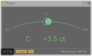
28.39.2 Classic View
In Classic View, the incoming pitch is represented as a colored ball along a curve, and the nearest detected note name is shown in the center of the display. The arrows on either side of the note name light up to indicate whether the signal needs to be tuned higher or lower in order to reach the desired pitch.
In Target Mode, a circular outline in the center of the curve shows the desired pitch, and your signal is in tune if the colored ball is exactly within this outline. If the incoming signal is sharp, the ball will appear to the right of the target, while flat signals will appear to the left.
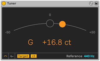
In Strobe Mode, the curve becomes a rotating band of lights. The direction of rotation indicates whether the signal is sharp or flat. If the band rotates to the right, the incoming pitch is sharp, while flat signals cause the band to rotate to the left. The further your signal is out of tune, the faster the band will move.
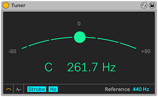
The Hertz/Cents Switch toggles between showing the absolute frequency of the incoming signal in Hertz or the distance from the target pitch in cents. This switch is also visible in the Histogram View.
28.39.3 Histogram View
In Histogram View, pitch is shown over time. The scale on the right of the display shows the possible note names, and the horizontal gray bars represent the perfectly in-tune “center” of the associated note. Sharp notes will appear above their corresponding gray line, while flat notes will appear below it.
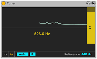
Drag up or down in the display to scroll to different pitches, or drag horizontally to zoom in or out. With Auto enabled, the display will automatically adjust so that the incoming pitch is in the center of the display.
The Hertz/Cents Switch toggles between showing the absolute frequency of the incoming signal in Hertz or the distance from the target pitch in cents. This switch is also visible in the Classic View.
28.39.4 Note Spellings
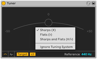
The Tuner device includes three options for note spellings. You can access a menu with these options when you right-click anywhere within Tuner’s view display:
- Sharps (C#)
- Flats (D♭)
- Sharps and Flats (C#/D♭)
28.39.5 Reference Slider
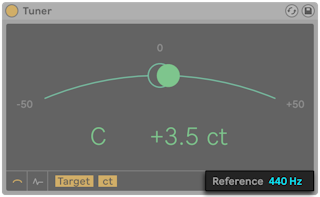
The Reference slider allows you to change the tuning reference that Tuner uses when analyzing incoming signals. By default this is set to 440 Hz, which is “standard” concert tuning, but it can be changed to any value between 410-480 Hz.
28.40 Utility
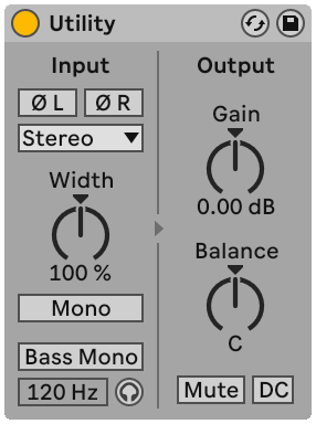
Utility can perform some very useful tasks, especially in combination with other devices.
There are two separate Phase controls, one for each input channel (Left and Right). As their names imply, they invert the phase of each channel.
The Channel Mode chooser allows selective processing of the left and right channels of a sample. If, for example, Left is selected, the right channel is ignored and the left channel appears on both outputs. This is especially useful if you have a stereo file that contains different information on both channels and you want to use only one.
The Width control sets the stereo width of the wet signal. 0% yields a mono signal whereas values above 100% create a widened stereo panorama.
Choosing Mid/Side Mode from the Width control’s context menu allows you to you toggle between the Width and Mid/Side controls. The Mid/Side control acts as a continuous mono to stereo controller when set from 0 to 100M. Setting the parameter to 100M will sum the audio to mono. Values between 0 and 100S emphasize the stereo or “out of phase” components of a signal. At 100S, only the side signal will be heard. The left and right channels will be 180 degrees out of phase with each other.
Note that if either Left or Right have been chosen in the Channel Mode chooser, the Width and Mid/Side controls have no function, and are therefore disabled.
When the Mono switch is enabled, the stereo input signal is converted to mono.
The Bass Mono switch converts the low frequencies of the input signal to mono. This is useful for avoiding coloration of low frequencies when they are replayed in mono. You can use the Bass Mono Frequency slider to adjust the cutoff frequency between 50-500 Hz.
When Bass Mono Audition is enabled, only the low frequencies can be heard. This can be useful for tuning the Bass Mono Frequency.
The Gain control adjusts the level of the input signal from -infinite dB to +35 dB. This can be particularly useful for automating volume fades on a track, while freeing up that track’s Volume control for mix balancing. When adjusting the Gain parameter between -18 and +35 dB using the up and down arrow keys, the value increases or decreases in 1 dB increments. However, between -18 dB and -inf dB, the value smoothly accelerates.
The Balance control pans the signal anywhere in the stereo field.
The Mute button simply silences the incoming signal when enabled. The active/mute controls of a track are always placed at the very end of the signal chain. However, since you can place Utility anywhere in a signal chain, you can use its mute function to cut the input of a delay line or reverb without turning off the output of these devices.
The DC switch filters out DC offsets and extremely low frequencies that are far below the audible range. It will only have a sonic effect if a signal contains these frequencies and is processed after Utility with nonlinear effects such as compressors or waveshapers.
28.41 Vinyl Distortion
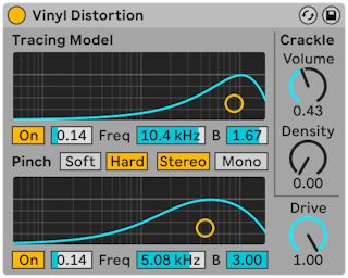
The Vinyl Distortion effect emulates some of the typical distortions that occur on vinyl records during playback. These distortions are caused by the geometric relationships between the needle and the recorded groove. The effect also features a crackle generator for adding noisy artifacts.
The Tracing Model section adds even harmonic distortion to the input signal. Adjust the amount of distortion with the Drive knob, or click and drag vertically in the Tracing Model X-Y display. To adjust the distortion’s frequency or ”color,” drag horizontally in the X-Y display or double-click on the Freq field and type in a value. Holding the Alt (Win) / Option (Mac) modifier while dragging vertically in the X-Y display changes the frequency band’s Q (bandwidth).
The Pinch Effect section adds odd harmonics to the input signal. These distortions typically occur 180 degrees out of phase, creating a richer stereo image. The Pinch Effect has the same controls as the Tracing Model, but generates a rather different sound.
The Drive control increases or decreases the overall distortion amount created by both the Tracing Model and Pinch.
There are two distortion modes: Soft and Hard. The Soft Mode simulates the sound of a dub plate, while Hard Mode is more like that of a standard vinyl record.
The stereo/mono switch determines whether the Pinch distortion occurs in stereo or mono. Set it to stereo for realistic simulation of vinyl distortions.
The Crackle section adds noise to the signal, with noise density set by the Density control. The Volume control adjusts the amount of gain applied to the noise.
28.42 Vocoder
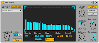
(Note: The Vocoder effect is not available in the Intro and Lite Editions.)
A vocoder is an effect that combines the frequency information of one audio signal (called the carrier) with the amplitude contour of another audio signal (called the modulator). The modulator source is generally something with a clear rhythmic character such as speech or drums, while the carrier is typically a harmonically-rich synthesizer sound such as a string or pad. The most familiar application of a vocoder is to create ”talking synthesizer” or robotic voice effects.
Vocoders work by running both the carrier and modulator signals through banks of band-pass filters. The output level of each of the modulator’s filters is then analyzed and used to control the volume of the corresponding filter for the carrier signal.
Live’s Vocoder should be inserted on the track that contains the audio material you plan to use as your modulator. The Carrier chooser then provides a variety of options for the carrier signal:
- Noise uses Vocoder’s internal noise generator as the carrier source. With this selected, an X-Y display is shown which allows you to adjust the character of the noise. The horizontal axis adjusts downsampling. Click and drag to the left to decrease the sample rate of the carrier’s output. The vertical axis adjusts the density of the noise. Click and drag downward to decrease the density.
- External allows you to select any available internal routing points from the choosers below. This is the option you’ll want for classic ”robot voice” applications.
- Modulator uses the modulator itself as the carrier. This essentially outputs a resynthesized version of the modulator signal, but allows you to use Vocoder’s sound-shaping controls to adjust the sound.
- Pitch Tracking enables a monophonic oscillator, which tunes itself to the pitch of the modulator. The High and Low sliders allow you to limit the frequency range that the oscillator will attempt to track. Choose from sawtooth or one of three pulse waveforms and adjust the coarse tuning of the oscillator via the Pitch slider. Pitch tracking is particularly effective with monophonic modulator sources such as melodic instruments or voices. Note that the oscillator only updates its frequency when it detects a clear pitch. It then maintains this pitch until it detects a new one. This means that changing the oscillator’s parameters or causing it to reset (when grouping Vocoder’s track, for example) can cause unexpected changes in the sound. With polyphonic material or drums, pitch tracking is generally unpredictable (but can be very interesting.)
Particularly when using external carrier sources, a vocoder’s output can sometimes lose a lot of high end. Enabling the Enhance button results in a brighter sound by normalizing the spectrum and dynamics of the carrier.
The Unvoiced knob adjusts the volume of an additional noise generator, which is used to resynthesize portions of the modulator signal that are pitchless, such as ”f” and ”s” sounds.
Sens. sets the sensitivity of the unvoiced detection algorithm. At 100%, the unvoiced noise generator is always on. At 0%, only the main carrier source is used. The Fast/Slow switch adjusts how quickly Vocoder switches between unvoiced and voiced detection.
Vocoder’s large central area shows the levels of the individual band-pass filters. Clicking within this display allows you to attenuate these levels.
The Bands chooser sets the number of filters that will be used. Using more bands results in a more accurate analysis of the modulator’s frequency content, but requires more CPU.
The Range sliders adjust the frequency range over which the band-pass filters will operate. For most sources, a fairly large range works well, but you may want to adjust the outer limits if the sound becomes too piercing or bassy. The BW control sets the bandwidth of the filters. At low percentages, each filter approaches a single frequency. As you increase the bandwidth, you increase the overlap of the filter bands. A bandwidth of 100% is the most accurate, but higher or lower settings can create interesting effects.
The Precise/Retro switch toggles between two types of filter behavior. In Precise mode, all filters have the same gain and bandwidth. In Retro mode, bands become narrower and louder at higher frequencies.
Gate sets a threshold for the filterbank. Any bands whose levels are below the threshold will be silent.
The Level slider boosts or cuts Vocoder’s output.
Depth sets how much of the modulator’s amplitude envelope is applied to the carrier’s signal. At 0%, the modulator’s envelope is discarded. At 200%, only high amplitude peaks will be used. 100% results in ”classic” vocoding.
The Attack and Release controls set how quickly Vocoder responds to amplitude changes in the modulator signal. Very fast times preserve the transients of the modulator, but can cause distortion artifacts.
The Mono/Stereo switches determine how many channels are used for the carrier and modulator. In Mono mode, both the carrier and modulator are treated as mono sources. Stereo uses a mono modulator but processes the carrier in stereo. L/R processes both the carrier and modulator signals in stereo.
The frequencies of the carrier’s filterbank can be shifted up or down via the Formant knob. With voice as the modulator, small Formant changes can alter the apparent gender of the source.
The Dry/Wet control adjusts the balance between the processed and dry signals.
28.42.1 Vocoder Tips
This section explains how to set up the most common Vocoder applications.
28.42.1.1 Singing Synthesizer
The classic vocoder application is the ”singing synthesizer.” To set this up in Live:
- Insert Vocoder in the track that contains your vocal material. You can either use a clip that contains a prerecorded voice clip or, to process a live vocal signal, connect a microphone to a channel on your audio hardware and choose this as the input source for the track.
- Insert a synthesizer such as Analog in another track. Again, you can either create a MIDI clip to drive this synthesizer or play it live.
- Set the vocoder’s Carrier chooser to External.
- Select the synthesizer track in the vocoder’s Audio From choosers. (For best results, choose Post FX in the bottom chooser.)
- If you’re creating your synthesizer and vocal material in real time, make sure the Arm button is enabled on both tracks.
- Play the synthesizer as you speak into the microphone. You’ll hear the rhythm of your speech, but with the timbral character and frequencies of the synthesizer. To hear the vocoded signal alone, solo the voice track so that the ”normal” synthesizer track is muted.
Note: you’ll generally get the best results if your synthesizer sound is bright and rich in harmonics. Try sawtooth-based patches to improve the intelligibility of the voice. For even more brightness and clarity, try adjusting the Unvoiced control and/or enabling Enhance.
28.42.1.2 Formant Shifter
If the Vocoder is set to use the modulator as its own carrier, it can be used as a powerful formant shifter. To do this:
- Set the Carrier chooser to Modulator.
- Set the Depth to 100%.
- Enable Enhance.
Now experiment with different settings of the Formant knob to alter the character of the source. For even more sound-sculpting possibilities, try adjusting the various filterbank parameters as well.